3. Proper
SIGNAL | PIN# | PIN# | SIGNAL |
TIP | 4 | 4 | TIP |
RING | 5 | 5 | RING |
4. Proper
SIGNAL | PIN# | PIN# | SIGNAL |
Tx | 4 | 3 | Rx |
Tx | 5 | 6 | Rx |
Rx | 3 | 4 | Tx |
Rx | 6 | 5 | Tx |
21
4.2 CONNECTING THE SERIAL PORT
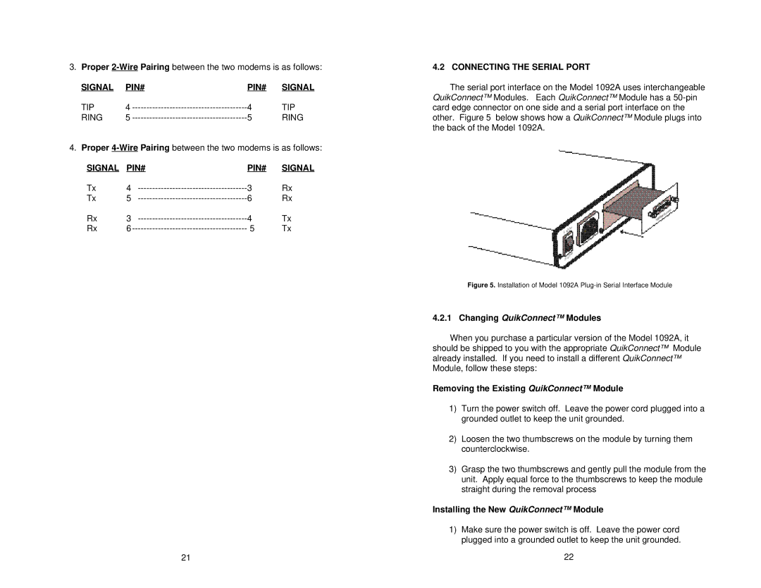
The serial port interface on the Model 1092A uses interchangeable QuikConnect™ Modules. Each QuikConnect™ Module has a
Figure 5. Installation of Model 1092A Plug-in Serial Interface Module
4.2.1 Changing QuikConnect™ Modules
When you purchase a particular version of the Model 1092A, it should be shipped to you with the appropriate QuikConnect™ Module already installed. If you need to install a different QuikConnect™ Module, follow these steps:
Removing the Existing QuikConnect™ Module
1)Turn the power switch off. Leave the power cord plugged into a grounded outlet to keep the unit grounded.
2)Loosen the two thumbscrews on the module by turning them counterclockwise.
3)Grasp the two thumbscrews and gently pull the module from the unit. Apply equal force to the thumbscrews to keep the module straight during the removal process
Installing the New QuikConnect™ Module
1)Make sure the power switch is off. Leave the power cord plugged into a grounded outlet to keep the unit grounded.
22
