3.2CONFIGURING THE SOFTWARE SWITCHES
The Model 1092A features a
1)Connect the serial
2)Power up the terminal and set its
9600 Baud
8 data bits, 1 stop bit, no parity Local echo
3)Power up the Model 1092A.
4)After the Model 1092A is powered on, the control port will send out this message:
Model: 1092A Software version: x.xx Patton Electronics Copyright (C) 2000
5)Press [ESC] on the terminal.
6)The 1092A will then display the MAIN MENU screen. You may configure the LOCAL Model 1092A from this screen.
Important!!: To make a selection from any menu, enter the option number. To exit any menu without making a selection, or to return to the previous menu, press the [ESC] key.
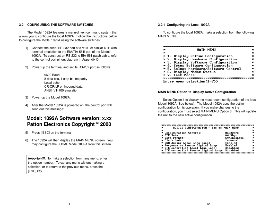
3.2.1 Configuring the Local 1092A
To configure the local 1092A, make a selection from the following
MAIN MENU.
MAIN MENU Option 1: Display Active Configuration
Select Option 1 to display the most recent configuration of the local Model 1092A (See below). The Model 1092A uses the active configuration for its operation. If you make changes to the configuration, you must select MAIN MENU Option 8. This will update the unit to the new active configuration.
11 | 12 |