APPENDIX C
PATTON ELECTRONICS MODEL 1092A INTERFACE PIN
ASSIGNMENT
(Continued)
V.35 Interface
(M/34F Female Connector)
(DCE Configuration)
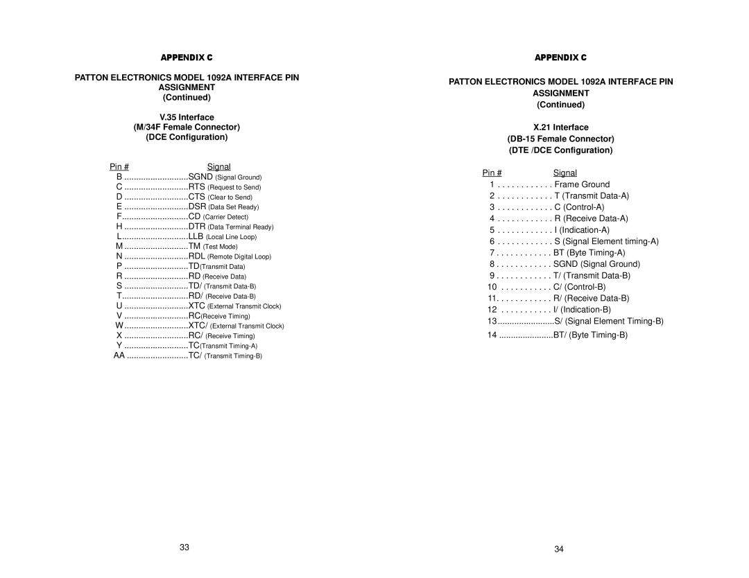
Pin # | Signal |
B | SGND (Signal Ground) |
C | RTS (Request to Send) |
D | CTS (Clear to Send) |
E | DSR (Data Set Ready) |
F | CD (Carrier Detect) |
H | DTR (Data Terminal Ready) |
L | LLB (Local Line Loop) |
M | TM (Test Mode) |
N | RDL (Remote Digital Loop) |
P | TD(Transmit Data) |
R | RD (Receive Data) |
S | TD/ (Transmit |
T | RD/ (Receive |
U | XTC (External Transmit Clock) |
V | RC(Receive Timing) |
W | XTC/ (External Transmit Clock) |
X | RC/ (Receive Timing) |
Y | TC(Transmit |
AA | TC/ (Transmit |
APPENDIX C
PATTON ELECTRONICS MODEL 1092A INTERFACE PIN
ASSIGNMENT
(Continued)
X.21 Interface
(DB-15 Female Connector)
(DTE /DCE Configuration)
Pin # | Signal |
1 | Frame Ground |
2 | T (Transmit |
3 | C |
4 | R (Receive |
5 | I |
6 | S (Signal Element |
7 | BT (Byte |
8 | SGND (Signal Ground) |
9 | T/ (Transmit |
10 | C/ |
11 | R/ (Receive |
12 | I/ |
13 | S/ (Signal Element |
14 | BT/ (Byte |
33 | 34 |
