especially into a 2 ohm load, will cause the breaker to trip. If this occurs, simply reset the breaker and correct the cause of the over- load. When tripped, the button on the breaker will be outward nearly 1/2" and can be reset by pushing inward. A normal reset button length is about 1/4". If this “thermal” type breaker does trip, then simply pushing the button back in will reset it after waiting a brief period of time to allow it to cool. If the breaker trips instantly when you attempt to reset it, the unit should be taken to a qualified serv- ice center for repair.
IEC MAINS POWER CONNECTOR (7)
The CS® 500A is fitted with a universal IEC connector. Into this connector one should always insert a
![]() conductor line cord with a conventional AC plug with a ground pin. This line cord should be connected to an independent mains circuit capable of supporting at least 15 amps continuously or greater. This is particularly critical for sustained high power applications. If the socket used does not have a ground pin, a suitable ground lift adapter should be used and the third wire grounded properly.
conductor line cord with a conventional AC plug with a ground pin. This line cord should be connected to an independent mains circuit capable of supporting at least 15 amps continuously or greater. This is particularly critical for sustained high power applications. If the socket used does not have a ground pin, a suitable ground lift adapter should be used and the third wire grounded properly.
Never break off the ground pin on the 3 conductor line cord. The use of extension cords should be avoided. If, however, their use is necessary, always use a
DDT™ SWITCH (8)
This switch is used to either ENABLE or DEFEAT the DDT™ compressor.
MODE SWITCH (9)
This switch is used to select either STEREO or BRIDGE mode of operation.
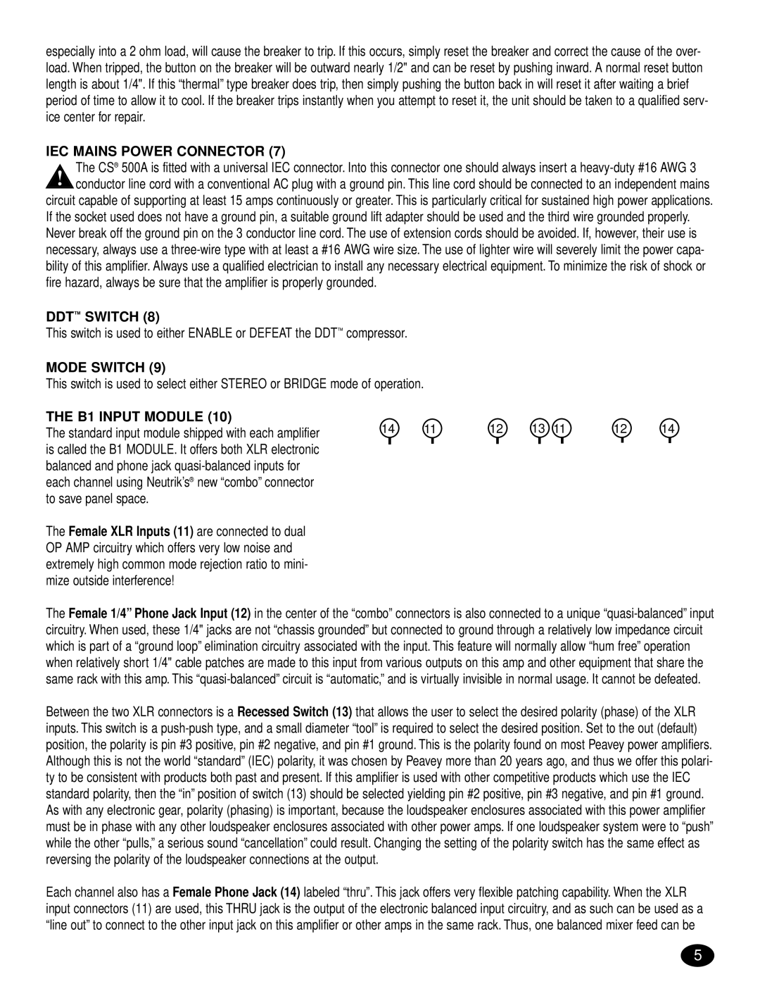
THE B1 INPUT MODULE (10) | 14 | 11 | 12 | 13 11 | 12 | 14 | |||||||
The standard input module shipped with each amplifier | |||||||||||||
is called the B1 MODULE. It offers both XLR electronic |
|
|
|
|
|
|
|
|
|
|
|
|
|
|
|
|
|
|
|
|
|
|
|
|
|
| |
balanced and phone jack |
|
|
|
|
|
|
|
|
|
|
|
|
|
each channel using Neutrik’s® new “combo” connector |
|
|
|
|
|
|
|
|
|
|
|
|
|
to save panel space. |
|
|
|
|
|
|
|
|
|
|
|
|
|
The Female XLR Inputs (11) are connected to dual OP AMP circuitry which offers very low noise and extremely high common mode rejection ratio to mini- mize outside interference!
The Female 1/4” Phone Jack Input (12) in the center of the “combo” connectors is also connected to a unique
Between the two XLR connectors is a Recessed Switch (13) that allows the user to select the desired polarity (phase) of the XLR inputs. This switch is a
Each channel also has a Female Phone Jack (14) labeled “thru”. This jack offers very flexible patching capability. When the XLR input connectors (11) are used, this THRU jack is the output of the electronic balanced input circuitry, and as such can be used as a “line out” to connect to the other input jack on this amplifier or other amps in the same rack. Thus, one balanced mixer feed can be
5