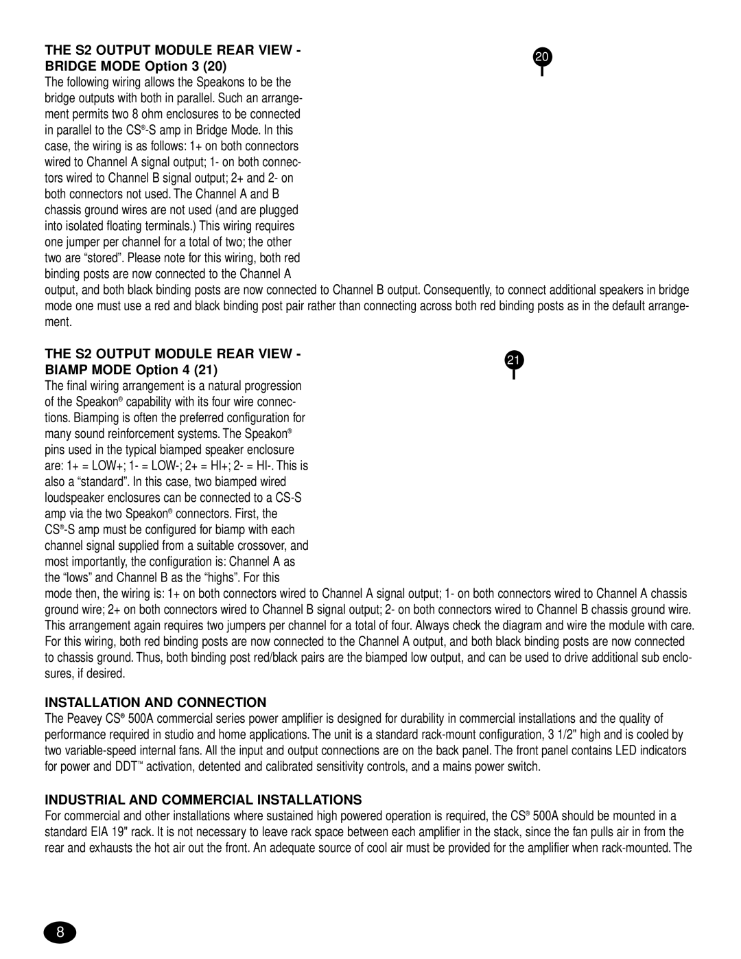
THE S2 OUTPUT MODULE REAR VIEW - | 20 | ||
BRIDGE MODE Option 3 (20) | |||
|
| ||
|
| ||
The following wiring allows the Speakons to be the |
|
| |
bridge outputs with both in parallel. Such an arrange- |
|
| |
ment permits two 8 ohm enclosures to be connected |
|
| |
in parallel to the |
|
| |
case, the wiring is as follows: 1+ on both connectors |
|
| |
wired to Channel A signal output; 1- on both connec- |
|
| |
tors wired to Channel B signal output; 2+ and 2- on |
|
| |
both connectors not used. The Channel A and B |
|
| |
chassis ground wires are not used (and are plugged |
|
| |
into isolated floating terminals.) This wiring requires |
|
| |
one jumper per channel for a total of two; the other |
|
| |
two are “stored”. Please note for this wiring, both red |
|
| |
binding posts are now connected to the Channel A |
|
| |
output, and both black binding posts are now connected to Channel B output. Consequently, to connect additional speakers in bridge
mode one must use a red and black binding post pair rather than connecting across both red binding posts as in the default arrange- | |||
ment. |
|
| |
THE S2 OUTPUT MODULE REAR VIEW - | 21 | ||
BIAMP MODE Option 4 (21) | |||
|
| ||
|
| ||
The final wiring arrangement is a natural progression |
|
| |
of the Speakon® capability with its four wire connec- |
|
| |
tions. Biamping is often the preferred configuration for |
|
| |
many sound reinforcement systems. The Speakon® |
|
| |
pins used in the typical biamped speaker enclosure |
|
| |
are: 1+ = LOW+; 1- = |
|
| |
also a “standard”. In this case, two biamped wired |
|
| |
loudspeaker enclosures can be connected to a |
|
| |
amp via the two Speakon® connectors. First, the |
|
| |
|
| ||
channel signal supplied from a suitable crossover, and |
|
| |
most importantly, the configuration is: Channel A as |
|
| |
the “lows” and Channel B as the “highs”. For this |
|
| |
mode then, the wiring is: 1+ on both connectors wired to Channel A signal output; 1- on both connectors wired to Channel A chassis ground wire; 2+ on both connectors wired to Channel B signal output; 2- on both connectors wired to Channel B chassis ground wire. This arrangement again requires two jumpers per channel for a total of four. Always check the diagram and wire the module with care. For this wiring, both red binding posts are now connected to the Channel A output, and both black binding posts are now connected to chassis ground. Thus, both binding post red/black pairs are the biamped low output, and can be used to drive additional sub enclo- sures, if desired.
INSTALLATION AND CONNECTION
The Peavey CS® 500A commercial series power amplifier is designed for durability in commercial installations and the quality of performance required in studio and home applications. The unit is a standard
INDUSTRIAL AND COMMERCIAL INSTALLATIONS
For commercial and other installations where sustained high powered operation is required, the CS® 500A should be mounted in a standard EIA 19" rack. It is not necessary to leave rack space between each amplifier in the stack, since the fan pulls air in from the rear and exhausts the hot air out the front. An adequate source of cool air must be provided for the amplifier when
8