U1002 specifications
The Peavey U1002 is a powerhouse in the realm of wireless audio solutions, designed to offer musicians and performers unparalleled flexibility and sound quality. As a part of Peavey's commitment to innovation and reliability, this wireless system is perfect for both live performances and studio applications.One of the standout features of the Peavey U1002 is its dual-channel operation, allowing users to connect two separate wireless microphones or devices simultaneously. This versatility is especially valuable for duets, group performances, or presentations, as it provides optimal freedom of movement without compromising audio quality. The system operates in the UHF frequency range, which is known for its minimal interference and superior signal clarity.
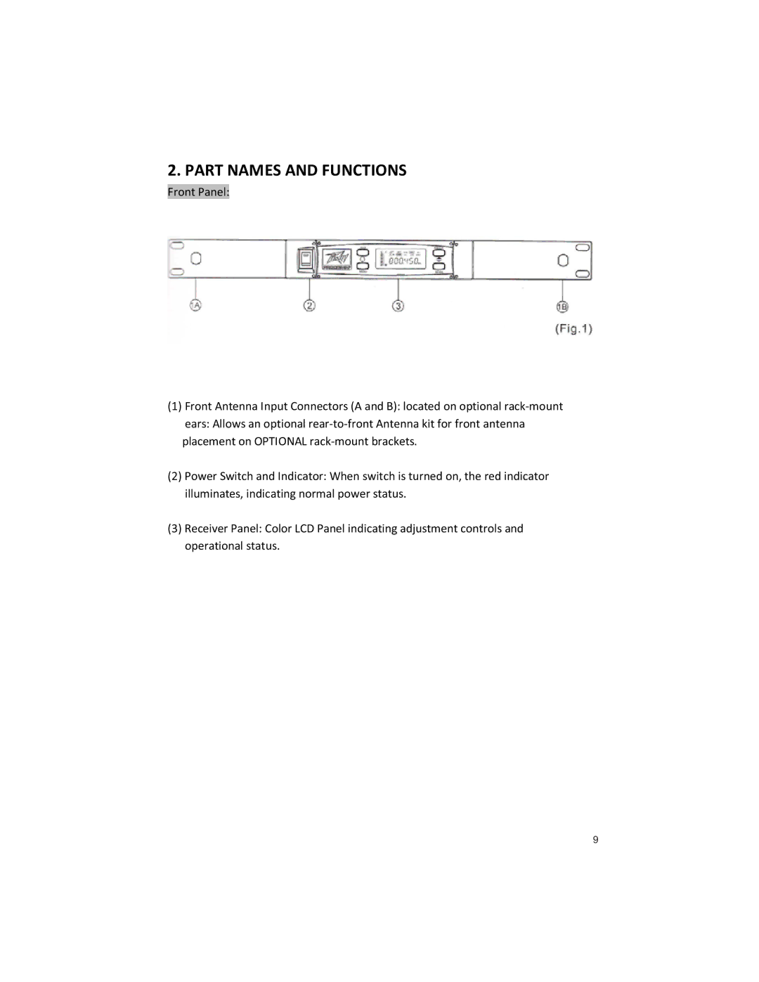
Another impressive aspect of the U1002 is its robust frequency response. It covers a wide range, ensuring that vocalists and instrumentalists achieve an authentic sound reproduction that captures the nuances of their performance. The inclusion of a digital display adds to the user-friendly experience, clearly showcasing the selected channel and battery status, allowing performers to maintain control during their sets without any confusion.
The automatic frequency scanning feature is also a game-changer. It detects and selects the best available channel, making setup quick and hassle-free. This technology is particularly beneficial in environments with multiple wireless systems in operation, as it minimizes the risk of interference and dropouts, ensuring reliable performance every time.
The U1002 is equipped with a high-quality microphone with a cardioid pickup pattern. This design enhances sound isolation and minimizes background noise, allowing the performer’s voice to shine through in any environment. Furthermore, the lightweight and ergonomic handheld design of the microphone ensures comfort during extended use, making it ideal for long gigs or events.
Battery life is another strong point of the U1002 system. With efficient power consumption, users can enjoy extended performance times, reducing the frequency of battery changes during shows. This reliability is crucial for professionals who rely on their equipment to deliver consistently high-quality sound.
In conclusion, the Peavey U1002 is a feature-rich wireless system that combines user-friendly technology with high performance. Its dual-channel capability, advanced frequency management, durable construction, and user-centric design make it an exceptional choice for musicians and presenters alike. Whether on stage or in the studio, the Peavey U1002 ensures that sound quality and ease of use remain paramount, establishing it as a go-to solution in the world of wireless audio.

