Manuals
/
Pelco
/
Household Appliance
/
Home Security System
Pelco
c3653m-a
manual
Sample S-EIDC-UGlobal Configuration, S-Eidc-U
Models:
c3653m-a
1
26
46
46
Download
46 pages
50.95 Kb
23
24
25
26
27
28
29
30
Output Indicator
Wiring S-EIDC-UDoor Components
Dimension
Input Configuration
Quick Mount Assembly
Powering Up An S-EIDC-U
Access Service Configuration
eFamily Update Procedure
Technical Features
Using This Manual
Page 26
Image 26
Page 25
Page 27
Page 26
Image 26
Page 25
Page 27
Contents
C3653M-A11/08
Hardware Installation And Reference
Pelco, Inc. Worldwide Headquarters
Preface
Trademarks
Table of Contents
Recessed Mounting Box
FCC Declaration Of Conformity S-EIDC-U, S-PCON-U
UL Compliance S-EIDC-U, S-PCON-U
Official Notices
Official Notices
Chapter 1 Intelli-M Hardware Overview Contents
Intelli-MHardware Overview Using This Manual
Intelli-MHardware Overview
S-EIDC-U
Using This Manual
Chapter 1 Intelli-MHardware Overview
Chapter 1 Intelli-MHardware Overview
ethernet Integrated Door Controller Contents
Chapter 2 S-EIDC-U
Technical Features
S-EIDC-UOverview
S-EIDC-U
Wiring S-EIDC-UDoor Components
S-EIDC-UDoor Component Wiring
Keep in mind the following points
Step 2: Wire the status, shunt, and exit inputs
Step 3 Wire the readers
Keep in mind the following points
Powering Up An S-EIDC-U
Four Power Options
Determining The Network IP Address Type
Setting A Static IP Address Within The S-EIDC-U
Setting A DHCP IP Address Within The S-EIDC-U
Setting An S-EIDC-UFor DHCP Addressing
Quick Mount Assembly Breakdown
Resetting An S-EIDC-U
Quick Mount Assembly
Page
S-PCON-UOverview
Chapter 3 S-PCON-U Power Connector Contents
Wiring And Powering Up S-PCON-U
Technical Features
S-PCON-UOverview
Wiring And Powering Up S-PCON-U
S-PCON-UWiring and Powering up Diagram
Chapter 3 S-PCON-UPower Connector
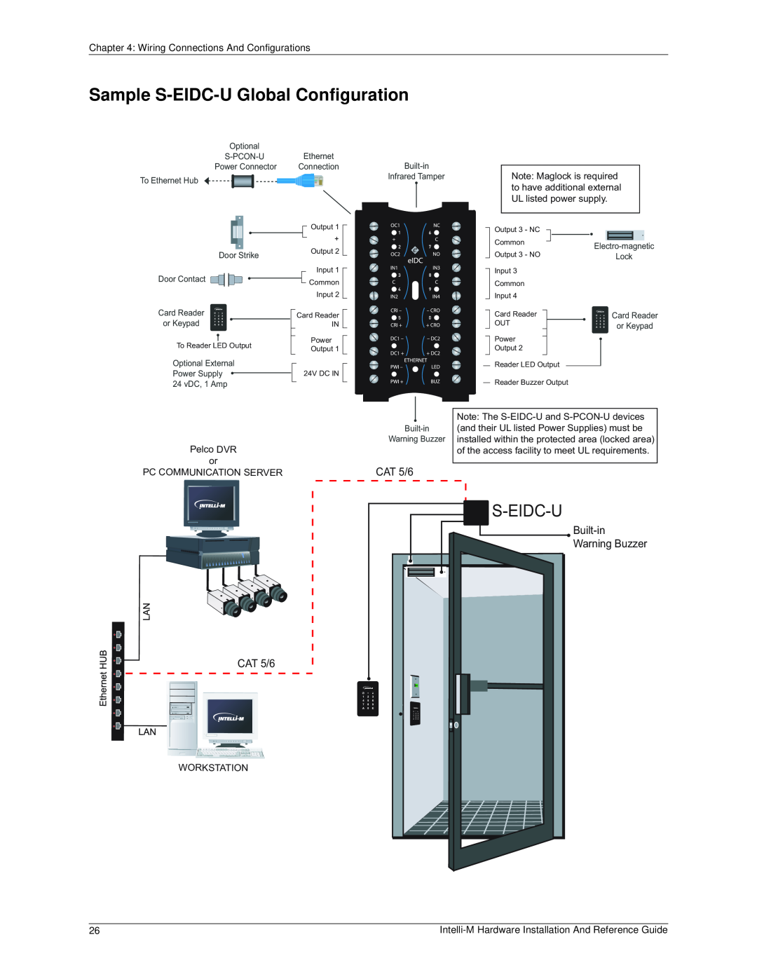
Sample S-EIDC-UGlobal Configuration
Chapter 4 Wiring Connections And Configurations
Contents
S-EIDC-UWiring Terminals
S-EIDC-U
Sample S-EIDC-UGlobal Configuration
Chapter 4 Wiring Connections And Configurations
S-EIDC-UWiring Terminals
Single Door Door Configuration With S-EIDC-U
S-EIDC-U
Installing The eFamily Update Utility
Appendix A eFamily Update Utility
Contents
eFamily Update Procedure
Supervisor Plus Users
Installing The eFamily Update Utility
2.Launch double click the “setup.exe” file
Web Interface Users
6.Click the “Close” button
eFamily Update Procedure
Before Updating Your eFamily Device
Figure A-7 Connection Information Screen
Figure A-6 Choice To Backup Screen
Figure A-5 Connection Information Screen
Page
Figure A-11 Connection Information Request Screen
Figure A-12 Update In Process Screen
Figure A-13 Update Complete Screen
Errors That Occur During Update
Figure A-14 Example Error Message
Page
Input Configuration
Appendix B Demo Kit Wiring
Defaults
Output Configuration
Alarm Service Configuration
Controller Configuration
Access Service Configuration
Quick Mount Assembly Kit Enclosure
S-EIDC-UTechnical Specifications
Dimensions
Ethernet Integrated Door Controller
Reader Ports
Power
Communication
Inputs
Dimensions
S-PCON-UTechnical Specifications Power Controller
Operational
Power Connector Module S-PCON-U
Power Out
Power In
DC Power --24 VDC, 1A
DC Power --22.9 to 24 VDC, 1A
Minimum Server Requirements
Miscellaneous Computer Hardware Specifications
Performance Communications Server Requirements
Performance Badging / Workstation Requirements
USB Camera WebCam
Minimum Badging / Workstation Requirements
Digital Camera
Signature Capture
Top
Page
Image
Contents