I/O UDP

Digital/Relay Section

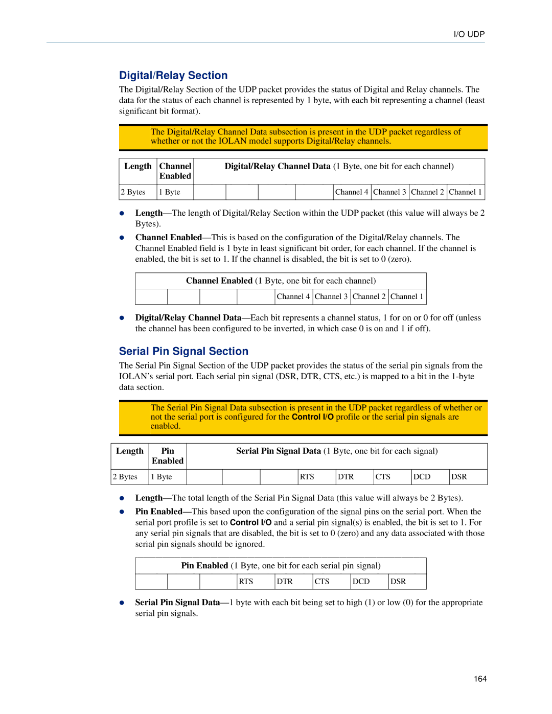
The Digital/Relay Section of the UDP packet provides the status of Digital and Relay channels. The data for the status of each channel is represented by 1 byte, with each bit representing a channel (least significant bit format).

Note: The Digital/Relay Channel Data subsection is present in the UDP packet regardless of whether or not the IOLAN model supports Digital/Relay channels.

Length

Channel

Digital/Relay Channel Data (1 Byte, one bit for each channel)


Enabled


2 Bytes

1 Byte


Channel 4

Channel 3

Channel 2

Channel 1


zLength—The length of Digital/Relay Section within the UDP packet (this value will always be 2 Bytes).

zChannel Enabled—This is based on the configuration of the Digital/Relay channels. The Channel Enabled field is 1 byte in least significant bit order, for each channel. If the channel is enabled, the bit is set to 1. If the channel is disabled, the bit is set to 0 (zero).

Channel Enabled (1 Byte, one bit for each channel)

Channel 4 Channel 3 Channel 2 Channel 1

zDigital/Relay Channel Data—Each bit represents a channel status, 1 for on or 0 for off (unless the channel has been configured to be inverted, in which case 0 is on and 1 if off).

Serial Pin Signal Section

The Serial Pin Signal Section of the UDP packet provides the status of the serial pin signals from the IOLAN’s serial port. Each serial pin signal (DSR, DTR, CTS, etc.) is mapped to a bit in the 1-byte data section.

Note: The Serial Pin Signal Data subsection is present in the UDP packet regardless of whether or not the serial port is configured for the Control I/O profile or the serial pin signals are enabled.

Length

Pin


Serial Pin Signal Data (1 Byte, one bit for each signal)


Enabled


2 Bytes

1 Byte


RTS

DTR

CTS

DCD

DSR


zLength—The total length of the Serial Pin Signal Data (this value will always be 2 Bytes).

zPin Enabled—This based upon the configuration of the signal pins on the serial port. When the serial port profile is set to Control I/O and a serial pin signal(s) is enabled, the bit is set to 1. For any serial pin signals that are disabled, the bit is set to 0 (zero) and any data associated with those serial pin signals should be ignored.

Pin Enabled (1 Byte, one bit for each serial pin signal)

RTS

DTR

CTS

DCD

DSR

zSerial Pin Signal Data—1 byte with each bit being set to high (1) or low (0) for the appropriate serial pin signals.

164

Page 164
Image 164
Perle Systems TS2, DS1 manual Digital/Relay Section, Serial Pin Signal Section, Length Channel, Length Pin

DS1, TS2 specifications

Perle Systems TS2 and DS1 are advanced serial-to-Ethernet devices designed to facilitate seamless integration of serial devices with modern IP networks. These devices serve as crucial tools for businesses looking to enhance their communication capabilities while leveraging existing infrastructure.

One of the standout features of the Perle TS2 and DS1 is their ability to support multiple serial protocols including RS232, RS422, and RS485. This versatile support allows businesses to connect various legacy devices to their networks, ensuring that critical equipment can still communicate effectively in an increasingly digital landscape.

The TS2 model is particularly noted for its dual serial ports, enabling simultaneous communication with multiple devices. This capability is invaluable for applications requiring real-time data transmission, such as remote monitoring and automated control systems. The DS1 model, on the other hand, is designed for single-port use, making it an ideal solution for smaller-scale operations or specific single-device connections.

Both the TS2 and DS1 incorporate advanced features such as configuration through a web interface, which simplifies setup and management. Users can easily access device settings and monitor performance metrics remotely, enhancing operational efficiency. These devices also support various network protocols such as TCP/IP, UDP, and ICMP, ensuring compatibility with a wide range of network architectures.

In terms of security, Perle Systems prioritize user data protection. The TS2 and DS1 offer features including SSL encryption and SSH protection, providing an added layer of security for sensitive information transmitted over the network. This is particularly important for industries where data integrity and security are paramount, such as healthcare and finance.

Additionally, the rugged design of both devices ensures reliable performance even in harsh environments. With extended temperature ratings and robust housing, the TS2 and DS1 can operate in diverse conditions without compromising functionality.

To summarize, the Perle Systems TS2 and DS1 provide a reliable and flexible solution for connecting legacy serial devices to modern networks. With their support for multiple serial protocols, web-based management, robust security features, and rugged design, these devices cater to a variety of industries looking to modernize their communication infrastructure while maintaining existing equipment. Whether for large-scale operations or smaller implementations, the TS2 and DS1 equip businesses with the tools needed for effective serial communication in an IP-driven world.