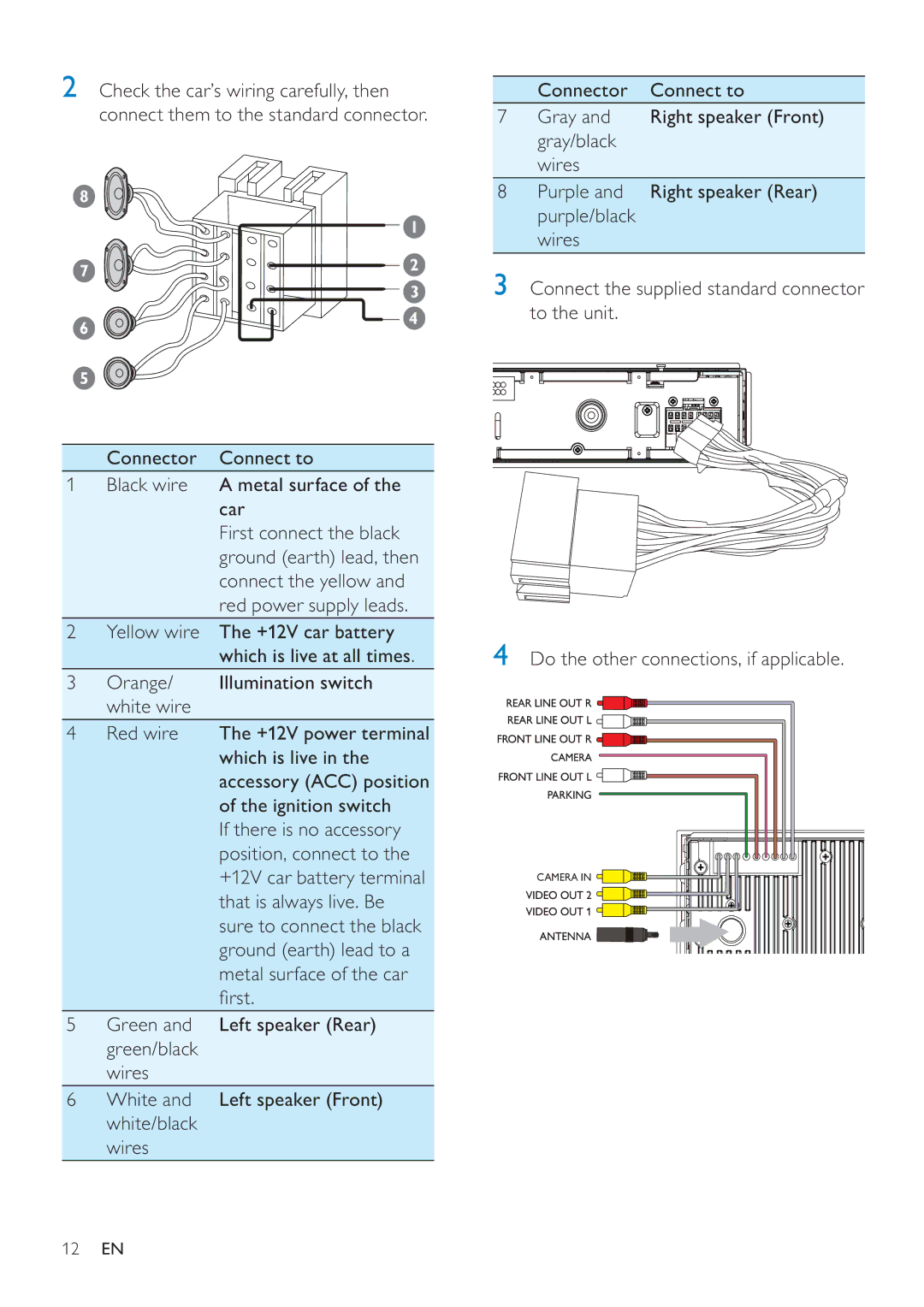
2Check the car’s wiring carefully, then connect them to the standard connector.
8
| 1 | |
7 | 2 | |
3 | ||
| ||
6 | 4 | |
| ||
5 |
|
Connector Connect to
1Black wire A metal surface of the car
First connect the black ground (earth) lead, then connect the yellow and red power supply leads.
2Yellow wire The +12V car battery which is live at all times.
3 | Orange/ | Illumination switch |
| white wire |
|
4 | Red wire | The +12V power terminal |
|
| which is live in the |
|
| accessory (ACC) position |
|
| of the ignition switch |
|
| If there is no accessory |
position, connect to the +12V car battery terminal that is always live. Be sure to connect the black ground (earth) lead to a metal surface of the car fi rst.
5Green and Left speaker (Rear) green/black
wires
6White and Left speaker (Front) white/black
wires
Connector Connect to
7Gray and Right speaker (Front) gray/black
wires
8Purple and Right speaker (Rear) purple/black
wires
3Connect the supplied standard connector to the unit.
4Do the other connections, if applicable.
CAMERA IN ![]()
![]()
12EN
