Colour Television Chassis
Contents
Technical Specifications
Technical Specifications, Connections, and Chassis Overview
Connection Overview
Cinch HD/CVI Audio
L06.1E
Cinch Video YPbPr
Cinch DVI Audio
PWB location
Chassis Overview
General
Safety Instructions, Warnings, and Notes
Safety Instructions
Maintenance Instructions
L06.1E Safety Instructions, Warnings, and Notes
Practical Service Precautions
Safety Instructions, Warnings, and Notes L06.1E
Alternative BOM identification
L06.1E Directions for Use
Directions for Use
Mechanical Instructions
Service Connector for IAP
Set Disassembly
Service Positions
L06.1E Mechanical Instructions Assy / Board Removal
Mains Switch/LED Panel
Top Control & Side I/O Assy/Panel
LSP locking handles
Set Re-assembly
Test Points
Service Modes, Error Codes, and Fault Finding
L06.1E Service Modes, Error Codes, and Fault Finding
Service Modes
How to store SAM settings
Service Modes, Error Codes, and Fault Finding L06.1E
How to Navigate
How to Exit
Service Tools
Problems and Solving Tips Related to CSM
Programming the Flash IC
Error Codes
How to Order
Installing the IAP software on a PC
Software Downloading
Blinking LED Procedure
Fault Finding and Repair Tips
Service Tips
Default Values Hex Dec Address dec 29PT9521/12 32PW9551/12
NVM default values
SAM
SAM Menu Structure
Speaker L
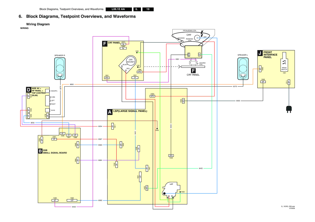
Block Diagrams, Testpoint Overviews, and Waveforms
Wiring Diagram
Speaker R CRT Socket
Power Supply
Block Diagram LSP Supply and Deflection
Testpoint Overview LSP
Video
Block Diagram Video
Audio
Block Diagram Audio
Panellink Receiver ERR
I2C Overview
ERR
+3V3STBY
Supply Line Overview
Supply Lines Overview
LSP Power Supply
Circuit Diagrams and PWB Layouts
Circuit Diagrams and PWB Layouts L06.1E AA
LSP Deflection
Deflection
CLASS-D
LSP Class D Audio Amplifier Res
Amplifier
LSP Audio Amplifier
LSP Tuner if Res
LSP Interfacing
A6 Interfacing
TER-CVBS-OUT
LSP Scart I/O Res
SC2-OUT
OUT
Layout LSP Top Side
G16350009c.eps G16350009d.eps
Layout LSP Overview Bottom Side
Part
G16350009a.eps G16350009b.eps
Layout LSP Part 1 Bottom Side
Part
Layout LSP Part 2 Bottom Side
Layout LSP Part 3 Bottom Side
Layout LSP Part 4 Bottom Side
SSB Power Supply & Connectivities
B1 Power Supply & Connectivities
Eeprom
Microprocessor
SSB Micro Processor
Eprom
SSB Tuner if & Demodulator
B3 Tuner if & Demodulator
Supplyana
SVPEX42
Analogifc
SSB DDR Dram & Supply
B5 DDR Dram & Supply
Sdram
For Test JIG
Hdmi
TV Display
SSB Deflection Controller
Processors
SSB Sound Processor
Sound Processor
Demodulator
SSB Scart Analogue I/O
Scart Analogue I/O
SSB Y, Pb, Pr, Ext. Input
B10
Analog Interface for
ADC
Flat Panel Display
Interpolation
SSB Hdmi Sound Switching
Filter
Layout SSB Top Side
Layout SSB Bottom Side
Side I/O Panel SL6
Side AV Panel + HP Panel + TOP Control SL6
Layout Side I/O Panel SL6 Bottom Side
Layout Side I/O Panel SL6 Top Side
LOT
CRT Panel
Scavem
Static Focus
Layout CRT Bottom Side
Layout CRT Panel Top Side
Interfacing
Front Interface Panel SL6
Input
Layout Front Interface Panel SL6 Bottom Side
Layout Front Interface Panel SL6 Top Side
Alignments L06.1E
Alignments
General Alignment Conditions
Hardware Alignments
Software Alignments
L06.1E Alignments
Alignment
Changing Multiple Options by Changing Option Byte Values
Option Settings
Changing a Single Option
Alignments
Option Settings
Option Bit Definition Opphilipstuner Philips Tuner
Opvirginmode Virgin Mode
General description of the SSB
Circuit Descriptions, Abbreviation List, and IC Data Sheets
Small Signal Board
Introduction
Software Upgrading Abbreviation List
DAF
FBL-TXT
FBX
DAC
LTI LTP LUT Lvds
IF-TER IIC
Irom IRQ ITV Jtag Keyb Keyboard
LSP
SNDL-SC1-IN
SOUND-ENABLE
Smps
SND
IC Data Sheets
Sets Listed
Spare Parts List
L06.1E Spare Parts List
Large Signal Panel a
Spare Parts List L06.1E
Software
Small Signal Board B
Spare Parts List L06.1E
L06.1E Spare Parts List
CRT Panel F
Side I/O and Control Board D
IAP Board
Front Interface Panel J
Revision List L06.1E
Revision List
Manual xxxx xxx
L06.1E Revision List