Mechanical Instructions | L06.1E |
| 4. |
| EN 9 |
4. Mechanical Instructions
Index of this chapter:
4.1Service Connector (for IAP)
4.2Set Disassembly
4.3Service Positions
4.4Assy / Board Removal
4.5Set
Note: Figures below can deviate slightly from the actual situation, due to the different set executions.
4.1Service Connector (for IAP)
For software uploading with the IAP tool (In Application Programming), it is not necessary to remove EEPROMs from the set. You only have to connect the IAP interface circuit to the service connector (on the rear of the set, and start the software uploading (see also chapter 5 "Service Modes, Error Codes, and Fault Finding").
4.2Set Disassembly
Follow the disassemble instructions in described order.
4.2.1Rear Cover Removal
Warning: disconnect the mains power cord before you remove the rear cover.
1.Remove all the fixation screws of the rear cover.
2.Now the rear cover can be removed.
4.3Service Positions
Only the LSP of this chassis has a service position for better access to the component side of the LSP. For the SSB, there is no specific service position.
4.3.1Large Signal Panel (LSP)
Component Side LSP
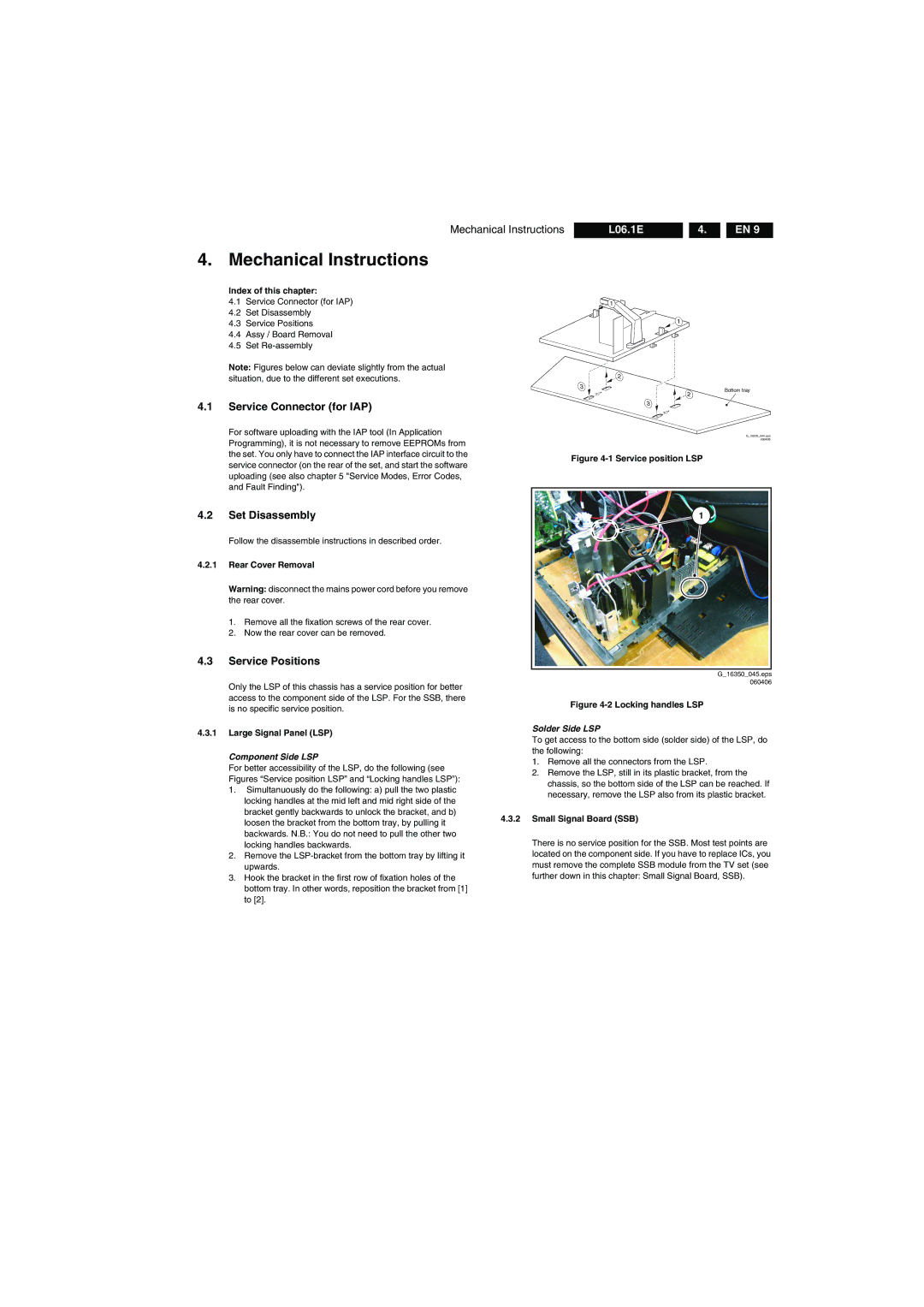
For better accessibility of the LSP, do the following (see Figures “Service position LSP” and “Locking handles LSP”):
1.Simultanuously do the following: a) pull the two plastic locking handles at the mid left and mid right side of the bracket gently backwards to unlock the bracket, and b) loosen the bracket from the bottom tray, by pulling it backwards. N.B.: You do not need to pull the other two locking handles backwards.
2.Remove the
3.Hook the bracket in the first row of fixation holes of the bottom tray. In other words, reposition the bracket from [1] to [2].
1
1
| 2 |
3 | Bottom tray |
| |
| 2 |
| 3 |
G_16350_044.eps 060406
Figure 4-1 Service position LSP
1 |
G_16350_045.eps 060406
Figure 4-2 Locking handles LSP
Solder Side LSP
To get access to the bottom side (solder side) of the LSP, do the following:
1.Remove all the connectors from the LSP.
2.Remove the LSP, still in its plastic bracket, from the chassis, so the bottom side of the LSP can be reached. If necessary, remove the LSP also from its plastic bracket.
4.3.2Small Signal Board (SSB)
There is no service position for the SSB. Most test points are located on the component side. If you have to replace ICs, you must remove the complete SSB module from the TV set (see further down in this chapter: Small Signal Board, SSB).