EN 60 |
| 8. |
| L06.1E | Alignments |
8.2.2Focus alignment
The LOT has the following outline:
–Focus 1 (F1) = Static alignment (red wire).
–Focus 2 (F2) = Dynamic alignment (white wire).
Service tip: When the set is equipped with a rotation coil, use this menu item to check its correct alignment. If alignment is not correct, go to the user MENU, choose FEATURES, and select ROTATION. With the use of a crosshatch test pattern, align it to a correct horizontal picture.
1.Use an external video pattern generator to input a "circle" or "crosshatch" test pattern to the set.
2.Choose "Natural" picture mode with the "Smart Picture" button on the remote control transmitter.
3.Adjust the "dynamic focus 2" potentiometer (in the middle on the LOT) until the horizontal lines at the centre of the screen are of minimum width without introducing a visible haze.
4.Adjust the "static focus 1" potentiometer (highest of the LOT) until the horizontal lines at the sides of the screen are of minimum width without introducing a visible haze.
5.Repeat these two steps to achieve the best result.
8.3Software Alignments
Put the set in the SAM (see the "Service Modes, Error Codes and Fault Finding" section). The SAM menu will now appear on the screen. The different alignment parameters are described further on.
Notes:
•All changes to menu items and alignments must be stored manually.
•If an empty EAROM (permanent memory) is detected, all settings are set to
8.3.1Tuner
AGC
1. | Set an external pattern generator to a colour bar video |
| signal and connect the RF output to the aerial input of the |
| TV. Set the amplitude to 10 mV and the frequency to |
| 475.25 MHz. Use system PAL B/G if possible, otherwise |
| match the system of your generator with the received |
| signal in the set. |
2. | Put the set in the SAM mode. |
3. | Select via the TUNER menu, the AGC |
4. | Connect a DC |
| pin). |
Alignment
1
2
3
4
5
6
7
8
9
10
11
12
VERT. SLOPE
VERT. SHIFT
VERT. AMPLITUDE
HOR. SHIFT
HOR. AMPLITUDE
E/W PARABOLE
UPPER E/W CORNER
LOWER E/W CORNER
E/W TRAPEZIUM
HOR. PARALLELOGRAM
HOR. BOW
E_06532_010.eps 110204
5. | Adjust the AGC until the voltage at pin 1 (F235, AGC pin) |
| of the tuner is 3.3 V (+/- 0.1 V). The value can be |
| incremented or decremented by pressing the right/left |
| CURSOR button on the RC. |
6. | After alignment, save the value(s) with the STORE |
| command in the SAM main menu. |
IF PLL OFFSET
No adjustments needed: default value (which can not be changed) is "0".
8.3.2Geometry
Notes:
•Set an external pattern generator to a crosshatch video signal and connect the RF output to the aerial input of the
TV. Set the amplitude at least 1 mVRMS (60 dBµV) and the frequency to 475.25 MHz. Use system PAL B/G if possible, otherwise match the system of your generator with the received signal in the set.
•Use the default alignment settings, but set "Brightness" to "32".
•For wide screen models, set to "wide screen" mode, for "classic" models, set to "4:3".
•After alignment, save the value(s) with the STORE command in the SAM main menu.
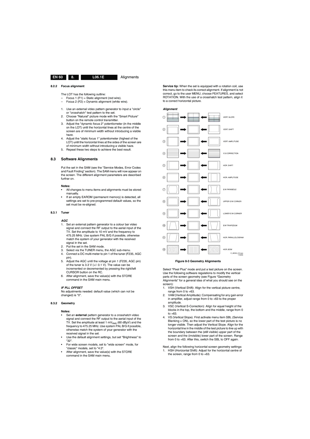
Figure 8-3 Geometry Alignments
Select “Pixel Plus” mode and put a test picture on the screen. Use the following software regulations to modify the vertical parts of the screen geometry (see Figure “Geometry Alignments” for a general idea of what you should see on the screen):
1.VSH (Vertical Shift): Align for the vertical picture centre, range from 0 to +63.
2.VAM (Vertical Amplitude): Compensating for any gain error in amplifier, adjust range from 0 to +63 to the proper amplitude.
3.VSC (Vertical
4.VS (Vertical Slope). First activate menu item SBL (Service Blanking = ON), so the lower part of the test picture is no longer visible. Then adjust the Vertical Slope. Align for the horizontal line in the middle of the test picture to line up with the boundery between the (still visible) upper part of the screen and the (invisible) lower part of the screen. Range from 0 to +63. After this, switch the SBL to OFF again.
Next, align the following horizontal screen geometry settings:
1.HSH (Horizontal Shift): Adjust for the horizontal centre of the screen, range from 0 to +63.