Connecting the Units
Note:
•This unit is for vehicles with a
•To avoid shorts in the electrical system, be sure to disconnect the ≠ battery cable before beginning installation.
•Refer to the owner’s manual for details on con- necting the power amp and other units, then make connections correctly.
•Secure the wiring with cable clamps or adhesive tape. To protect the wiring, wrap adhesive tape around them where they lie against metal parts.
•Route and secure all wiring so it cannot touch any moving parts, such as the gear shift, handbrake, and seat rails. Do not route wiring in places that get hot, such as near the heater outlet. If the insu- lation of the wiring melts or gets torn, there is a danger of the wiring
•Don’t pass the yellow lead through a hole into the engine compartment to connect to the battery. This will damage the lead insulation and cause a very dangerous short.
•Do not shorten any leads. If you do, the protection circuit may fail to work when it should.
•Never feed power to other equipment by cutting the insulation of the power supply lead of the unit and tapping into the lead. The current capacity of the lead will be exceeded, causing overheating.
•When replacing a fuse, be sure to use only fuses of the rating prescribed on the fuse holder.
•The black lead is ground. Please ground this lead separately from the ground of
If you ground the products together and the ground becomes detached, there is a risk of dam- age to the products or fire.
•When this product’s source is switched ON, a control signal is output through the blue/white lead. Connect to an external power amp’s system remote control or the car’s
•When an external power amp is being used with this system, be sure not to connect the blue/white lead to the amp’s power terminal. Likewise, do not connect the blue/white lead to the power ter- minal of the
•To avoid
•To prevent incorrect connection, the input side of the
•Connection of this system requires optical cables and
•Set GPS antenna away from this unit. If you set them too close, it may fail to operate properly.
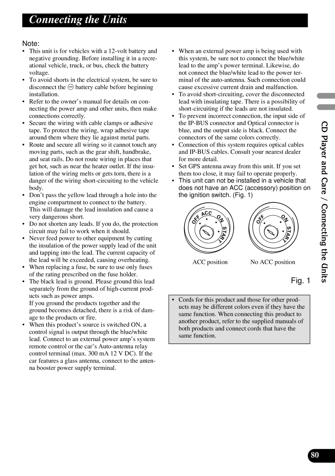
•This unit can not be installed in a vehicle that does not have an ACC (accessory) position on the ignition switch. (Fig. 1)
|
| CC |
|
|
|
|
|
|
|
|
| F | A | O |
|
|
| F | O |
|
|
|
| N |
| F | N | |||||
O | F |
|
|
|
| O |
|
|
| |
|
|
|
| S |
|
|
| S | ||
|
|
|
|
|
|
|
|
| ||
|
|
|
|
| T |
|
|
|
| T |
|
|
|
| R | A |
|
|
| R | A |
|
|
| T |
|
|
| T |
| ||
|
|
|
|
|
|
|
|
| ||
ACC position | No ACC position | |||||||||
Fig. 1
•Cords for this product and those for other prod- ucts may be different colors even if they have the same function. When connecting this product to another product, refer to the supplied manuals of both products and connect cords that have the
same function.
CD Player and Care / Connecting the Units
80