DVH-3950MP
Contents
Thank you for buying this Pioneer product
English
Avchd recorded discs
Discs and player
Safety note
Precautions of handling
When using a display
To avoid battery exhaustion
To ensure safe driving
About this unit
About the Symbol Display
Visit our website
Region code
Types of Playable Discs
Features
About WMA
Symbols used in this manual
About MP3 About DivX
Control Panel
What’s What
Remote control What’s What
Mute
Remote control
BAND/TAB
Remote control Battery installation
Using the remote control
Before use Detaching control panel
Attaching control panel
Before use TV system selection
Basic operation Turning the unit on
Ejecting a disc
Turning the unit off
Selecting a source
Basic operation Adjusting the volume
Setting the clock
Using the EQ Equalizer
Mute
Basic operation Adjusting the sound level
Changing the general settings
To scan the preset stations
To tune in the preset stations
Radio operation Listening to radio stations
Auto search memory
Playing an Audio CD and MP3/WMA disc
12 3
CD/MP3/WMA operation
Pause
Search
Skip to next track/file
To skip to the next or previous folder
07 CD/MP3/WMA operation
Shuffle
SET UP menu
Language
Menu Language
Disc Audio/Subtitle/Menu
SET UP menu Display
Audio
TV Aspect
E. Black Level Expansion
Password
Lock Parental Control
Dynamic Range Control DRC
Rating
Area Code
If you forget your password
Others
DivX VOD
Pre-Stop
DVD/VCD operation Displaying Disc Information on-screen
Playing a DVD and Video CD
DVD/VCD operation
Stop
Still picture and frame-by- frame playback
Slow motion
Skip to next chapter/track
Skip to previous chapter/track
Scan
Return to the beginning of the current chapter/track
Time search
Disc menu DVD
PBC menu VCD
Camera angle DVD
DVD/VCD operation Changing the audio language DVD
Changing the audio channel VCD
Subtitles DVD
Zoom
Viewing slide shows
PAL
Photo operation
Moving to another folder
Viewing still picture
Moving to another file
Playing a movie file
Movie operation Playing DivX VOD content
Movie operation
Skip
Changing the audio language
Subtitles
AUX operation Playing an auxiliary equipment
Installation
Installation with the rubber bush
DIN front/rear mount
DIN Front-mount
DIN Rear-mount
Connection
ACC position
Connection Connecting to a car
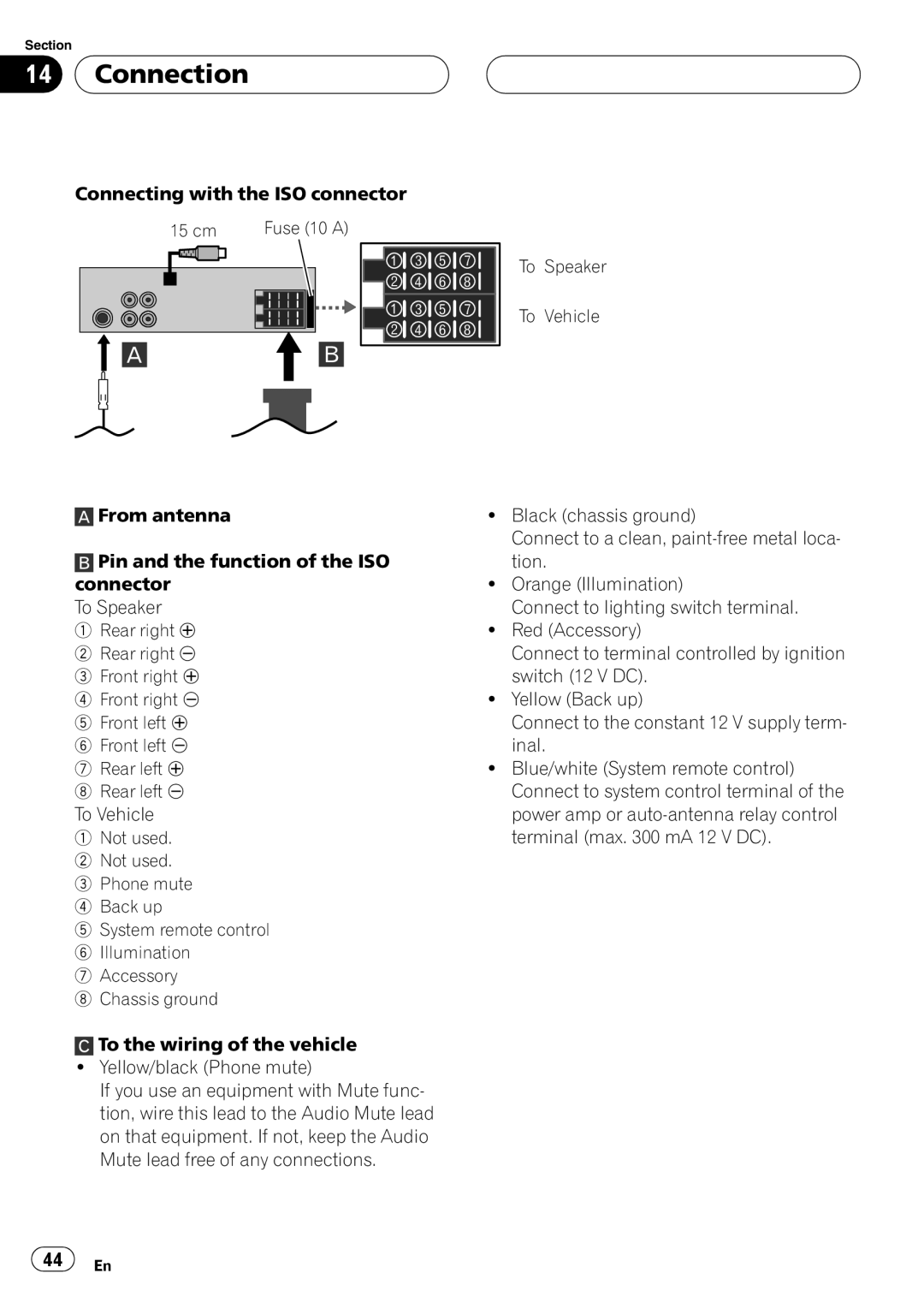
15 cm
Connecting with the ISO connector
Connection
Connection Connecting to auxiliary equipment Optional
Connection
Additional Information Troubleshooting
Symptom Cause Action
DVD discs
DVD-R/DVD-RW discs
Avchd recorded discs
CD-R/CD-RW discs
Compressed audio files on the disc
Additional Information
Dual Discs
DivX video files
Example of a hierarchy
Additional Information Language code list
Language and the code
Additional Information Area code list
Area and the code
Additional Information Specifications
General
Dolby Digital/DTS/MPEG
Rating Password
關於 WMA 關於 MP3 關於 DivX
Area Code 77 Others PBC DivX VOD
DVD Chapter/Title/Off VCD Track/All
DIN 前座
DIN 後座
階層實例 DivX視頻檔案 語言代碼清單 100 區域代碼清單
重要安全措施
01 安全注意事項
處理光碟與播放器的注意事項
安全注意事項 行駛安全注意事項
使用顯示幕時
防止電池耗盡
歡迎造訪本公司網站
DVD Format/Logo Licensing Corporation 的商標。
01 安全注意事項 區域代碼的注意事項
可播放光碟的類型
安全注意事項
本手冊使用的符號
關於 DivX
本的 DivX 視訊(包括 DivX)。 中 ! 「DivX」、「DivX Certified」 和相關標 文
02 控制面板
按鈕功能
遙控器 按鈕功能
03 遙控器
遙控器 安裝電池
使用遙控器
選擇電視系統
拆下控制面板
裝上控制面板
使用前
05 基本操作 開啟本機
關閉本機
插入光碟
選擇播放源
基本操作
設定時鐘
使用EQ(等化器)
變更一般設定
05 基本操作
廣播操作 收聽廣播電台
自動搜尋記憶體
預設電台檢索
儲存廣播頻率
07 CD/MP3/WMA 操作
本機的 MP3/WMA 光碟相容性 受以下限制:
播放音樂 CD 和 MP3/WMA 光碟
(音樂CD)、3 000個(MP3/WMA)和251個
跳至下一個曲目/檔案
跳至上一個曲目/檔案
回到目前曲目/檔案的開頭
移動到其他曲目/檔案
跳至前一個或次一個資料夾 MP3 WMA
設定選單
Display Language
E.(黑階延伸)
08 設定選單
Lock(成人控制)
如果忘記密碼
選擇DivX VOD選項然後按d。
DVD/VCD 操作
在螢幕上顯示光碟資訊
播放 DVD 和 VCD
預先停止
靜態影像和逐格播放
慢動作
移動到其他標題 DVD
移動至其他章節/曲目
時間搜尋
跳到上一個章節/曲目
回到目前章節/曲目的開頭
光碟選單 DVD
變更音訊語言 DVD
變更音訊頻道 VCD
字幕 DVD
(或低於2 760 × 2 048 像素),並另外
圖片操作 本播放器的JPEG/TIFF光碟相容 性受以下限制:
檢視幻燈片
10 圖片操作 移動到其他資料夾
移動到其他檔案
幻燈片間隔時間
檢視靜態圖像
播放DivX VOD內容
影片操作 本播放器的 DivX 光碟相容性受 以下限制:
播放影片檔案
11 影片操作
顯示 DivX 字幕的注意事項
影片操作
變更音訊語言
按遙控器上SUBTITLE以選擇其他字元集, 直到字幕正常顯示為止。
AUX 操作
播放輔助設備
DIN 前/後座
DIN 前座
DIN 後座
14 連接
連接至車輛
14 連接
Zhtw
連接到輔助設備(選配)
附加資訊 故障排除
雙面碟
附加資訊 光碟與播放器的操作指南
Avchd 格式錄製的光碟
附加資訊
碟片上的壓縮音頻檔案
DivX視頻檔案
與ISO 9660 Level 1與2相容。Romeo與Jo
附加資訊 語言代碼清單
輸入正確的初始設定代碼編號Disc Audio、 SUBTITLE及/或Menu(請參閱第75頁)。
附加資訊 區域代碼清單
輸入正確的初始設定代碼編號Area Code(請 參閱第77頁)。
FM調諧器
CD TEXT/ID3 TAG
Language
Disc Audio/Subtitle/Menu
Display
Area Code Others PBC DivX VOD
PBC 메뉴 VCD
Page
01 안전 주의 사항
디스크와 플레이어의 취급 시 주 의 사항
안전 주의 사항
중요 안전 수칙
디스플레이를 사용할 경우
배터리 소진을 피하려면
01 안전 주의 사항 웹사이트 방문
기호 표시에 대하여
지역 코드
지역 코드 관련 참고 사항
WMA에 대하여
DTS 및 DTS Digital Out은 DTS, Inc
설명서에서 사용되는 기호
MP3에 대하여
제어 패널
부분 명칭
03 리모컨
리모컨
배터리 설치 리모컨 사용
사용하기 전에 탈착식 제어 패널
제어 패널 장착
04 사용하기 전에 TV 시스템 선택
기본 조작 기기 전원 켜기 디스크 꺼내기
기기 전원 끄기
음원 선택
디스크 넣기
05 기본 조작 음량 조정
음소거
시계 설정
사운드 강화
기본 조작
일반 설정 변경
06 라디오 조작 라디오 방송 청취
방송국 주파수 저장
자동 검색 메모리
사전 설정 방송국을 스캔하려면
CD/MP3/WMA 조작
기기의 MP3/WMA 디스크 호환 성은 다음과 같이 제한됩니다
오디오 CD와 MP3/WMA 디스크 재생
×4, ×8, m ×4, ×8
일시 정지
다음 트랙/파일로 건너뛰기
이전 트랙/파일로 건너뛰기
도입부 스캔
다음 또는 이전 폴더로 건너뛰려면
SET UP 메뉴
Lock영상물 잠금 제어
E.검정 레벨 확장
암호를 잊어 버린 경우
Show Code가 선택된 상태에서 ENT를 누
DVD/VCD 조작
화면에 디스크 정보 표시
DVD 및 비디오 CD 재생
재생 중지
정지 영상 및 프레임 단위 재생
슬로우 모션
다른 타이틀로 이동 DVD
다른 챕터/트랙으로 이동
다음 챕터/트랙으로 건너뛰기
이전 챕터/트랙으로 건너뛰기
현재 챕터/트랙의 시작 부분으 로 되돌아가기
×8, n ×16, n ×32, n ×100앞으 로
시간 검색
디스크 메뉴 DVD
PBC 메뉴 VCD
카메라 앵글 DVD
자막 DVD
오디오 언어 변경 DVD
오디오 채널 변경 VCD
Tiff 파일의 해상도를 2M 픽셀, 2 760 ×
사진 조작 플레이어의 JPEG/TIFF 디스크 호 환성은 다음과 같이 제한됩니다
슬라이드 쇼 보기
10 사진 조작
다른 폴더로 이동
다른 파일로 이동
슬라이드 쇼 간격 시간
동영상 조작 플레이어의 DivX 디스크 호환 성은 다음과 같이 제한됩니다
동영상 파일 재생
16, t 1/8, t 1/4 또는 t 1/2앞으로
11 동영상 조작
DivX VOD 콘텐츠 재생
오디오 언어 변경
동영상 조작
건너뛰기
DivX 자막 표시에 대한 참고 사항
AUX 사용
보조 장비 재생
DIN 전방 장착
DIN 전방/후방 장착
DIN 후방 장착
14 연결
차량에 연결
14 연결
최대 300mA 12V DC
Page
보조 장비옵션에 연결
추가 정보 문제 해결
추가 정보 디스크와 플레이어의 취급 안내
DVD 디스크
DVD-R/DVD-RW 디스크
Avchd 기록 디스크
디스크의 압축된 오디오 파일
추가 정보
듀얼 디스크
추가 정보 DivX 비디오 파일
DivX VOD 파일을 재생하려면 DivX VOD
추가 정보 언어 코드 목록
언어 및 코드
추가 정보 지역 코드 목록
초기 설정 Area Code 초기 설정을 위해 적절 한 코드 번호를 입력합니다127 페이지 참조
추가 정보 제품 사양
일반적인 내용
Pioneer Corporation

 Connection