NAMES AND FUNCTIONS OF PARTS
22 MIDI OUT connector | 23 MIDI USB output connector |
DIN type output connector. | |
Use to connect to other MIDI component. |
|
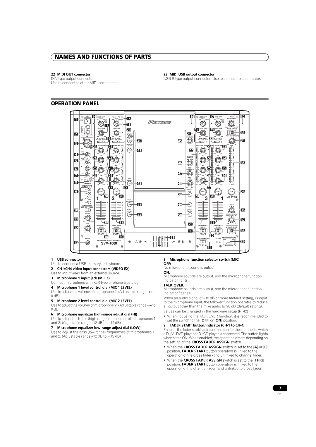
OPERATION PANEL
1 |
| 14 VIDEO INPUT |
| VIDEO INPUT | 15 | 16 |
| VIDEO INPUT | 17VIDEO INPUT |
| VIDEO | 32 | ||||||||||||||
USB |
|
| DVD VIDEO | DVD VIDEO |
|
| DVD VIDEO |
|
|
| DVD VIDEO | MASTER LEVEL | ||||||||||||||
|
|
| VIDEO |
|
|
|
|
|
|
|
|
|
|
|
|
|
|
|
| VIDEO |
|
| ||||
|
|
|
|
|
| EX |
|
|
|
|
| 18 |
|
|
|
|
|
|
|
|
|
|
| EX |
|
|
| CH 1 |
|
| VIDEO TRIM | 18 | VIDEO TRIM |
|
| 18 | VIDEO TRIM |
| 18 | VIDEO TRIM | BLACK | WHITE | |||||||||||
| VIDEO |
|
|
|
|
| 20 |
|
|
| MONO STEREO | |||||||||||||||
| EX |
|
|
|
|
|
|
|
|
|
| 21 |
|
|
|
|
|
|
|
| 33 | |||||
2 | CH 4 |
|
|
|
|
|
|
|
|
|
|
|
|
|
|
|
|
|
|
|
|
|
|
| ||
|
|
|
|
|
|
|
|
|
|
| UTILITY |
|
|
|
|
|
|
|
|
|
|
|
| |||
MIC |
|
| MIN | MAX | MIN |
| MAX | MASTER | MIN |
| MAX |
|
| MIN | MAX AUDIO MASTER LEVEL | |||||||||||
|
|
|
| MONITOR | CH SELECT |
|
|
| ||||||||||||||||||
|
|
|
| AUDIO INPUT | AUDIO INPUT | SET UP |
|
| AUDIO INPUT |
|
|
| AUDIO INPUT |
|
|
| ||||||||||
|
|
|
|
|
|
|
|
|
|
|
|
| ||||||||||||||
|
|
| DVD/LINE PHONO 19 DVD | LINE | DIGITAL | 40 | 45 | DVD | LINE | DIGITAL 22 | LINE PHONO |
|
| 34 | ||||||||||||
3 |
|
|
|
|
|
|
|
|
|
|
|
|
|
|
|
|
|
|
|
|
|
|
| |||
|
| 23 | AUDIO TRIM OVER | 23 | AUDIO TRIM OVER | VIDEO EQ |
| OVER | AUDIO TRIM | 23 | OVER | AUDIO TRIM | 23 | OVER | 0 | |||||||||||
|
|
| ON/OFF |
|
| |||||||||||||||||||||
|
|
|
|
|
|
|
|
|
| SET UP |
|
|
|
|
|
|
|
|
|
|
| |||||
| MIC 1 |
|
|
|
|
|
|
|
| 41 | 27 |
|
|
|
|
|
|
|
|
|
| |||||
4 | MIC1 |
|
|
|
| 10 |
|
|
|
| 10 | 10 |
|
|
|
|
|
| 10 |
|
|
| 10 |
| ||
LEVEL |
|
|
| +9 | 7 |
|
|
| +9 | 7 |
|
| 7 |
|
| +9 |
|
|
| 7 |
| +9 |
| 7 |
| |
|
| 24 |
| HI | 4 | 24 |
| HI |
| 4 |
| VIDEO FX | 4 |
| HI |
| 24 |
| 4 |
| HI | 24 | 4 |
| ||
| MIC2 | 0 |
|
| 2 |
|
|
| 2 |
| PATTERN/ | 2 |
|
|
|
| 2 |
|
| 2 |
| |||||
|
|
|
|
|
|
|
|
|
|
|
|
|
|
| ||||||||||||
5 |
|
|
|
|
|
|
|
|
| TEXT BANK |
|
|
|
|
|
|
|
|
|
| ||||||
LEVEL |
|
|
| 1 |
|
|
| 1 |
| 1 |
|
|
|
| 1 |
|
| 1 |
| |||||||
|
|
|
|
|
|
|
|
| 46 |
|
|
|
|
|
|
|
|
| 35 | |||||||
|
| 0 |
| +6 | 0 |
|
| +6 | 0 |
| 0 |
| +6 |
|
|
| 0 | +6 |
| 0 | ||||||
|
|
|
|
|
|
|
|
|
|
| ||||||||||||||||
| HI |
|
|
| MID |
|
| MID |
|
|
|
| MID |
|
|
|
|
| MID |
|
| |||||
6 |
| 25 |
|
| 25 |
|
|
|
|
|
|
|
| 25 |
|
|
| 25 |
| |||||||
|
|
|
|
|
|
|
| TIME/ |
|
|
|
|
|
|
| |||||||||||
|
|
|
|
|
|
|
|
|
|
|
|
|
|
|
|
|
|
|
| |||||||
+12 |
|
|
|
|
|
| PARAMETER |
|
|
|
|
|
|
| ||||||||||||
|
|
|
|
|
|
|
|
| 47 |
|
|
|
|
|
|
|
|
|
| |||||||
| LOW |
|
|
|
|
|
|
|
|
|
|
|
|
|
|
|
|
|
|
| ||||||
7 |
| 26 | +6 |
| 26 |
| +6 |
|
|
| +6 | 26 |
| +6 | 26 |
|
| |||||||||
|
|
|
|
|
|
| ||||||||||||||||||||
+12 |
| LOW |
| LOW |
|
| LEVEL/ | LOW |
|
|
| LOW |
| |||||||||||||
|
|
|
|
|
|
|
|
|
| JPEG |
|
|
|
|
|
|
|
|
|
|
|
|
| |||
|
| TALK |
|
|
|
|
|
|
| DEPTH |
|
|
|
|
|
|
|
|
| |||||||
8 | MIC OFF ON OVER |
|
|
|
|
|
|
|
|
| VIEWER |
|
|
|
|
|
|
|
|
|
|
|
|
|
| |
|
|
|
|
|
|
|
|
| 42 | 48 |
|
|
|
|
|
|
|
| ||||||||
FADER START |
| +6 | dB |
|
| +6 | dB | dB |
| +6 |
|
| dB |
| +6 |
| L dB | R | ||||||||
|
|
|
|
| 27 |
|
|
|
| 27 | MIN MAX |
|
|
|
| 27 |
|
|
|
|
|
|
| |||
|
|
|
|
|
|
|
|
|
|
|
|
|
|
|
|
|
|
|
|
|
| |||||
| CH1 |
|
|
|
|
|
|
|
|
| EFFECT |
|
|
|
|
|
|
|
|
|
|
| ||||
9 |
|
|
|
|
|
|
|
|
|
|
|
|
|
|
|
|
|
|
|
|
|
|
|
| 28 | |
|
|
|
| CUE |
|
|
| CUE |
|
|
| CUE |
|
| CUE |
|
|
|
|
|
| CUE |
| CUE | ||
CH2 |
|
|
|
|
|
|
|
|
|
|
| 28 |
|
|
|
|
|
|
|
|
|
|
|
| ||
|
|
| 1 | 28 | 2 |
| 28 |
| 28 |
|
| 3 | 28 |
| 4 | MASTER | ||||||||||
| CH3 |
|
| VIDEO |
|
|
|
| ||||||||||||||||||
| CH4 |
|
|
|
| 10 |
|
|
|
| 10 | SOLO MODE |
| 10 |
|
|
|
|
| 10 |
|
|
|
|
|
|
|
|
|
|
|
|
|
|
| 43 | 49 |
|
|
|
|
|
|
|
|
|
|
| |||||
|
|
|
|
|
| 9 |
|
|
|
| 9 | 9 |
|
|
|
|
| 9 |
|
|
|
| BALANCE | |||
| HEAD PHONES |
|
|
| 8 |
|
|
|
| 8 | 8 |
|
|
|
|
| 8 |
|
|
|
| |||||
|
|
|
|
|
|
|
|
|
|
|
|
|
|
|
|
|
|
| ||||||||
| MONO SPLIT | STEREO |
|
|
| 7 |
|
|
|
| 7 |
|
| 7 |
|
|
|
|
| 7 |
|
|
|
|
| 36 |
10 |
|
|
|
|
| 6 |
|
|
|
| 6 | FADER | EFFECT | 6 |
|
|
|
|
| 6 |
|
|
|
|
| |
|
|
|
|
| 5 |
|
|
|
| 5 | 5 |
|
|
|
|
| 5 |
|
|
|
|
| ||||
|
|
|
|
|
|
|
|
| AV SYNC | ON/OFF |
|
|
|
|
|
|
|
|
|
| ||||||
|
|
|
|
| 4 |
|
|
|
| 4 | 4 |
|
|
|
|
| 4 |
|
|
|
|
| ||||
| MIXING |
|
|
|
|
|
|
|
|
|
|
|
|
|
|
|
|
|
| L | R | |||||
|
|
|
| 3 |
|
|
|
| 3 | 44 | 50 | 3 |
|
|
|
|
| 3 |
|
|
|
| BOOTH MONITOR | |||
|
|
|
|
|
| 2 |
|
|
|
| 2 | 2 |
|
|
|
|
| 2 |
|
|
|
| ||||
|
|
|
|
|
| 1 |
|
|
|
| 1 | 1 |
|
|
|
|
| 1 |
|
|
|
|
|
| ||
11 |
|
|
|
|
|
|
|
|
|
|
|
|
|
|
|
|
|
|
|
|
|
| ||||
|
|
|
|
| 0 |
|
|
|
| 0 |
|
| 0 |
|
|
|
|
| 0 |
|
|
|
|
| 37 | |
CUE | MASTER |
| 29 |
|
|
| 29 |
|
|
|
|
|
|
| 29 |
|
|
|
| |||||||
|
|
|
|
|
| 29 |
|
|
|
|
|
|
|
|
|
| ||||||||||
| LEVEL |
|
|
|
|
|
|
|
|
|
|
|
|
|
|
| 0 | |||||||||
12 |
|
| CROSS FADER | CROSS FADER |
| CROSS FADER |
|
| CROSS FADER |
|
| |||||||||||||||
|
|
| ASSIGN |
|
| ASSIGN |
|
|
|
| ASSIGN |
|
|
|
| ASSIGN | CH FADER CURVE | |||||||||
|
|
|
|
|
|
|
|
|
|
|
| 30 |
|
|
|
|
|
|
|
|
|
|
|
| 38 | |
|
| 0 |
|
|
|
|
|
|
|
|
|
|
|
|
|
|
|
|
|
|
|
|
|
| ||
|
|
|
| A | THRU B |
|
| A | THRU | B |
|
| 51 |
| A | THRU | B |
| 30 A | THRU B |
|
|
| |||
| PHONES |
|
| 30 |
|
|
| 30 |
| CROSS FADER CURVE |
|
|
| SD CARD |
|
| 39 | |||||||||
13 |
|
|
| PROFESSIONAL SOUND&VISION MIXER | A | B |
|
|
|
|
|
|
|
|
|
|
|
| ||||||||
|
|
|
|
|
|
|
|
|
|
|
|
|
|
|
|
|
| |||||||||
|
|
|
|
|
|
|
|
|
|
|
|
|
|
|
|
|
|
|
|
| ||||||
|
|
|
|
|
|
|
|
|
|
|
|
|
|
|
|
|
| 31 |
|
|
|
|
|
| ||
1 USB connector
Use to connect a USB memory or keyboard.
2CH1/CH4 video input connectors (VIDEO EX) Use to input video from an external source.
3Microphone 1 input jack (MIC 1)
Connect microphone with
4 Microphone 1 level control dial (MIC 1 LEVEL)
Use to adjust the volume of microphone 1. (Adjustable range
5 Microphone 2 level control dial (MIC 2 LEVEL)
Use to adjust the volume of microphone 2. (Adjustable range
6 Microphone equalizer high-range adjust dial (HI)
Use to adjust the treble
7 Microphone equalizer low-range adjust dial (LOW)
Use to adjust the bass
8 Microphone function selector switch (MIC) OFF:
No microphone sound is output.
ON:
Microphone sounds are output, and the microphone function indicator lights.
TALK OVER:
Microphone sounds are output, and the microphone function indicator flashes.
When an audio signal of
Values can be changed in the hardware setup (P. 42)
•When not using the TALK OVER function, it is recommended to set the switch to the [OFF] or [ON] position.
9 FADER START button/indicator (CH-1 to CH-4)
Enables the fader start/back cue function for the channel to which
aDJ/VJ DVD player or DJ CD player is connected. The button lights when set to ON. When enabled, the operation differs depending on the setting of the CROSS FADER ASSIGN switch.
•When the CROSS FADER ASSIGN switch is set to the [A] or [B] position, FADER START button operation is linked to the operation of the cross fader (and unlinked to channel fader).
•When the CROSS FADER ASSIGN switch is set to the [THRU] position, FADER START button operation is linked to the operation of the channel fader (and unlinked to cross fader).
7
En