NAMES AND FUNCTIONS OF PARTS
NAMES AND FUNCTIONS OF PARTS
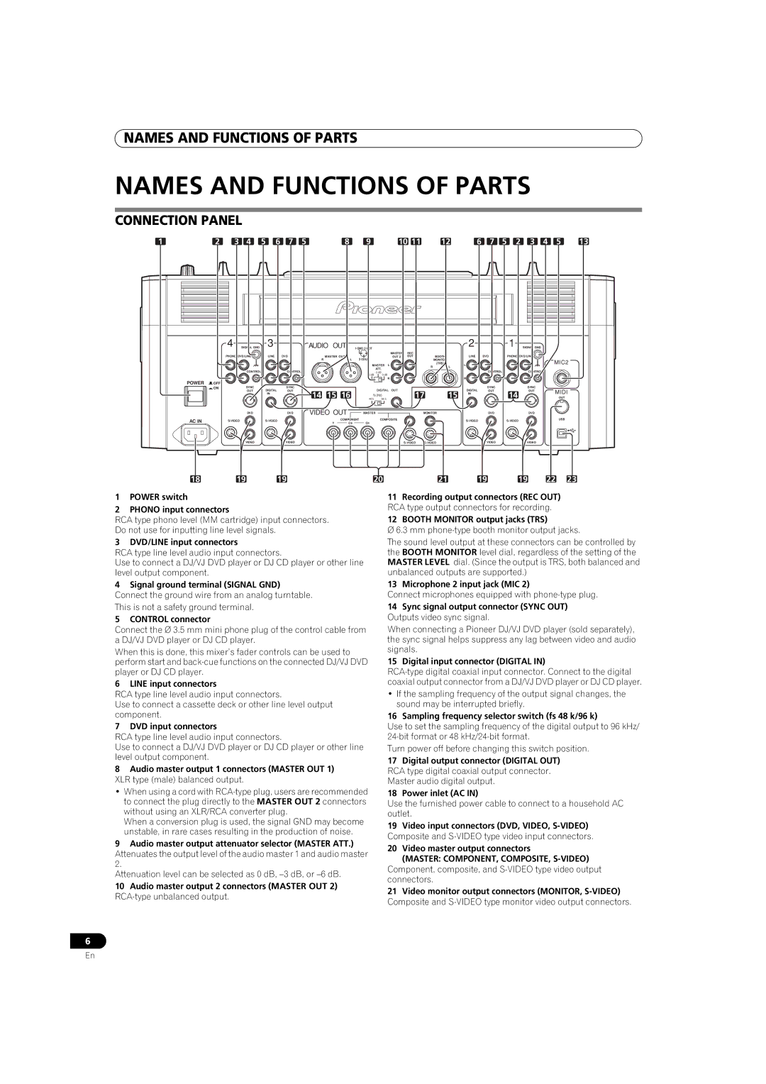
CONNECTION PANEL
1 | 2 | 3 | 4 | 5 | 6 | 7 | 5 |
| 8 | 9 |
|
| 10 11 |
| 12 | 6 | 7 | 5 | 2 | 3 | 4 | 5 | 13 | ||
| 4 |
| SIGNAL GND |
| 3 |
|
| AUDIO OUT |
| 1 GND 2 HOT |
|
|
|
|
|
| 2 |
|
| 1 | SIGNAL GND |
|
|
| |
|
|
|
|
|
|
|
|
|
|
|
|
|
| MASTER | REC |
|
|
|
|
|
|
|
|
|
|
| PHONO DVD/LINE |
| LINE | DVD |
| R | MASTER OUT 1 | L | 3 COLD |
|
| OUT 2 | OUT |
| BOOTH | LINE | DVD |
| PHONO DVD/LINE |
|
|
| |||
|
|
|
|
|
|
|
|
|
|
|
|
|
| MONITOR |
|
|
|
|
|
| MIC2 | ||||
| L |
|
| L |
|
|
|
|
|
| MASTER | L |
|
|
| (TRS) | L |
| L |
|
|
| |||
|
|
|
|
|
|
|
|
|
|
| R | L |
|
|
|
|
|
| |||||||
|
|
| CONTROL |
|
| CONTROL |
|
|
|
|
| ATT. |
|
|
|
|
|
| CONTROL |
| CONTROL |
|
|
| |
|
|
|
|
|
|
|
|
|
|
|
|
|
|
|
|
|
|
| |||||||
|
|
|
|
|
|
|
|
|
|
| 0 dB |
|
|
|
|
|
|
|
|
|
|
|
|
| |
POWER | R |
|
| R |
|
|
|
|
|
|
|
| R |
|
|
|
| R |
| R |
|
|
|
|
|
OFF |
|
|
|
|
|
|
|
|
|
|
|
|
|
|
|
|
|
|
|
|
|
|
|
| |
| ON |
| SYNC | DIGITAL | SYNC |
|
|
|
|
| DIGITAL | OUT |
|
|
| DIGITAL | SYNC |
|
| SYNC |
| MIDI | |||
|
|
| OUT | OUT |
| 14 | 15 16 |
| 17 | 15 | OUT |
| 14 | OUT |
| ||||||||||
|
|
|
|
| IN |
|
| fs (Hz) |
|
| IN |
|
|
|
| ||||||||||
|
|
|
|
|
|
|
|
|
|
|
|
|
|
| OUT |
| |||||||||
|
|
|
|
|
|
|
| 48 k | 96 k |
|
|
|
|
|
|
|
| ||||||||
|
|
| DVD |
|
| DVD |
| VIDEO OUT |
| MASTER |
|
|
| MONITOR |
| DVD |
|
| DVD |
|
|
| |||
AC IN |
|
|
|
| COMPONENT | COMPOSITE |
|
|
|
|
|
|
| USB |
| ||||||||||
|
|
|
| Y | CB | CR |
|
|
|
|
|
|
|
|
|
|
|
| |||||||
|
|
|
|
|
|
|
|
|
|
|
|
|
|
|
|
|
|
|
|
|
| ||||
|
|
| VIDEO |
|
| VIDEO |
|
|
|
|
|
|
|
|
| VIDEO |
|
| VIDEO |
|
|
| |||
18 |
| 19 |
| 19 |
|
|
|
| 20 |
|
|
|
| 21 | 19 |
| 19 | 22 | 23 | ||||||
1POWER switch
2PHONO input connectors
RCA type phono level (MM cartridge) input connectors. Do not use for inputting line level signals.
3 DVD/LINE input connectors
RCA type line level audio input connectors.
Use to connect a DJ/VJ DVD player or DJ CD player or other line level output component.
4Signal ground terminal (SIGNAL GND) Connect the ground wire from an analog turntable. This is not a safety ground terminal.
5CONTROL connector
Connect the Ø 3.5 mm mini phone plug of the control cable from a DJ/VJ DVD player or DJ CD player.
When this is done, this mixer’s fader controls can be used to
perform start and
6 LINE input connectors
RCA type line level audio input connectors.
Use to connect a cassette deck or other line level output component.
7 DVD input connectors
RCA type line level audio input connectors.
Use to connect a DJ/VJ DVD player or DJ CD player or other line level output component.
8Audio master output 1 connectors (MASTER OUT 1) XLR type (male) balanced output.
•When using a cord with
When a conversion plug is used, the signal GND may become unstable, in rare cases resulting in the production of noise.
9Audio master output attenuator selector (MASTER ATT.)
Attenuates the output level of the audio master 1 and audio master
Attenuation level can be selected as 0 dB,
10Audio master output 2 connectors (MASTER OUT 2)
11Recording output connectors (REC OUT) RCA type output connectors for recording.
12BOOTH MONITOR output jacks (TRS)
Ø 6.3 mm
The sound level output at these connectors can be controlled by the BOOTH MONITOR level dial, regardless of the setting of the MASTER LEVEL dial. (Since the output is TRS, both balanced and unbalanced outputs are supported.)
13 Microphone 2 input jack (MIC 2)
Connect microphones equipped with
14Sync signal output connector (SYNC OUT) Outputs video sync signal.
When connecting a Pioneer DJ/VJ DVD player (sold separately), the sync signal helps suppress any lag between video and audio signals.
15 Digital input connector (DIGITAL IN)
•If the sampling frequency of the output signal changes, the sound may be interrupted briefly.
16 Sampling frequency selector switch (fs 48 k/96 k)
Use to set the sampling frequency of the digital output to 96 kHz/
Turn power off before changing this switch position.
17Digital output connector (DIGITAL OUT) RCA type digital coaxial output connector. Master audio digital output.
18Power inlet (AC IN)
Use the furnished power cable to connect to a household AC outlet.
19Video input connectors (DVD, VIDEO,
20Video master output connectors
(MASTER: COMPONENT, COMPOSITE, S-VIDEO)
Component, composite, and
21Video monitor output connectors (MONITOR,
6
En