Connecting up | 02 |
1Pull off the protective shields of both AM antenna wires.
2Push open the tabs, then insert one wire fully into each terminal, then release the tabs to secure the AM antenna wires.
3Fix the AM loop antenna to the stand. To fix the stand to the antenna, bend in the direction indicated by the arrow (fig. a) then clip the loop onto the stand (fig. b).
•If you plan to mount the AM antenna to a wall or other surface, secure the stand with screws (fig. c) before clipping the loop to the stand. Make sure the reception is clear.
4Place the AM antenna on a flat surface and point in the direction giving the best reception.
Don’t let it come into contact with metal objects and avoid placing near computers, television sets or other electrical appliances.1
5Connect the FM wire antenna in the same way as the AM loop antenna.
For best results, extend the FM antenna fully and fix to a wall or door frame. Don’t drape loosely or leave coiled up.
Connecting external antennas
External AM antenna
Use
| Outdoor antenna | |
Indoor | ANTENNA | |
antenna | ||
AM LOOP | ||
ANTENNA | ||
wire) | ||
| ||
| FM | |
| UNBAL | |
| 75Ω |
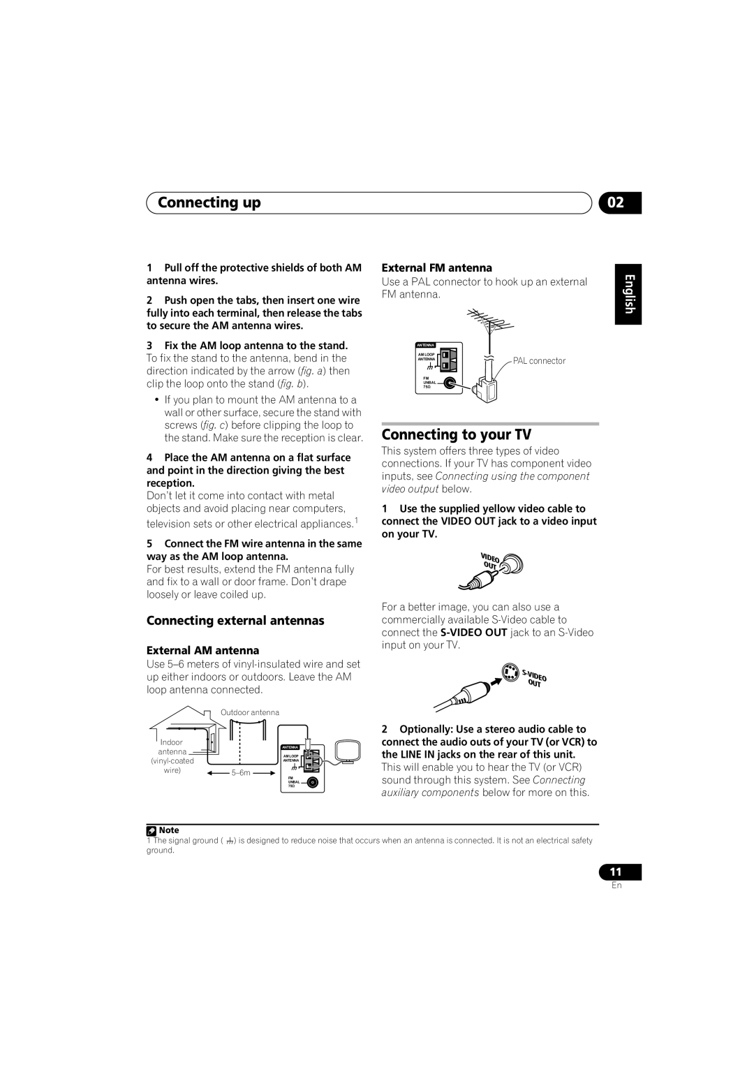
External FM antenna
Use a PAL connector to hook up an external FM antenna.
ANTENNA |
|
AM LOOP | PAL connector |
ANTENNA | |
FM |
|
UNBAL |
|
75Ω |
|
Connecting to your TV
This system offers three types of video connections. If your TV has component video inputs, see Connecting using the component video output below.
1Use the supplied yellow video cable to connect the VIDEO OUT jack to a video input on your TV.
VIDEO
OUT 
For a better image, you can also use a commercially available
![]()
OUT
2Optionally: Use a stereo audio cable to connect the audio outs of your TV (or VCR) to the LINE IN jacks on the rear of this unit. This will enable you to hear the TV (or VCR) sound through this system. See Connecting
auxiliary components below for more on this.
English Deutsch Français Italiano Nederlands Español
![]() Note
Note
1 The signal ground ( ) is designed to reduce noise that occurs when an antenna is connected. It is not an electrical safety ground.
11
En