INSTALLATION GUIDES
CAUTION: Before any installation or cable connection to the set, please always make certain that the system is turned off and the external power source to the set is removed to prevent electric hazard! Never touch any metal pin in the connectors or circuits to avoid high voltage hazard or electrostatic discharge damage unless the operator is well grounded. Failure to do the above will void the product warranty!
OPENING CABLE COVER
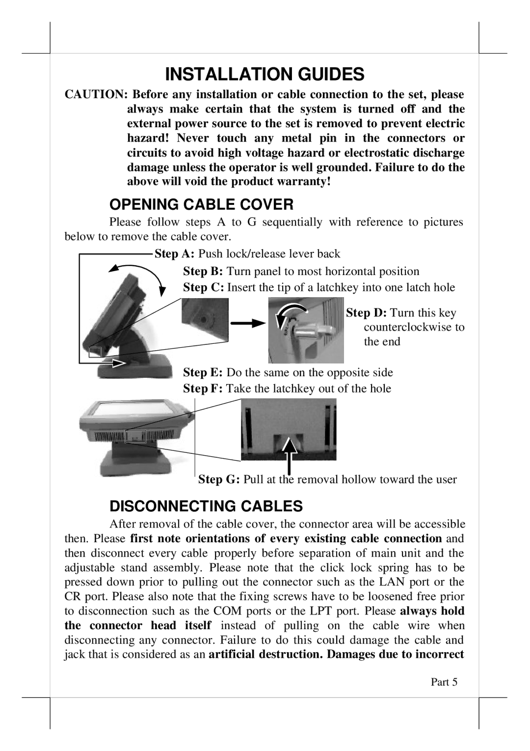
Please follow steps A to G sequentially with reference to pictures below to remove the cable cover.
Step A: Push lock/release lever back
Step B: Turn panel to most horizontal position Step C: Insert the tip of a latchkey into one latch hole
Step D: Turn this key counterclockwise to the end
Step E: Do the same on the opposite side
Step F: Take the latchkey out of the hole
Step G: Pull at the removal hollow toward the user
DISCONNECTING CABLES
After removal of the cable cover, the connector area will be accessible then. Please first note orientations of every existing cable connection and then disconnect every cable properly before separation of main unit and the adjustable stand assembly. Please note that the click lock spring has to be pressed down prior to pulling out the connector such as the LAN port or the CR port. Please also note that the fixing screws have to be loosened free prior to disconnection such as the COM ports or the LPT port. Please always hold the connector head itself instead of pulling on the cable wire when disconnecting any connector. Failure to do this could damage the cable and jack that is considered as an artificial destruction. Damages due to incorrect
Part 5