![]() A chipbreaker set too low or with excessive tension may prevent stock from feeding into the machine.
A chipbreaker set too low or with excessive tension may prevent stock from feeding into the machine.
Pressure Bar
Most planing problems can be traced to improper setting of the pressure bar. Its function is to hold down the material after it passes under the cutterhead and throughout the remainder of the cut. Its basic setting is to be in line with the arc of the cutterhead knives.
If it is too high, a shallow “clip” will occur at each end of the board. If it is too low, stock will not feed through.
Use a gauge to set the full length of the pressure bar to
Outfeed Rollers
The two outfeed rollers are of smooth,
Use a gauge, such as a bed and feed roll gauge or wood gauge block, to check the outfeed rollers in the same manner as the infeed roller.
Adjust as necessary using the screws (F, Figure 11). When finished adjusting, tighten the hex nuts on the screws (F, Figure 11).
Table Rollers
The Planer has two table rollers which help reduce friction of the stock on the table as it feeds through the machine. It is not possible to give exact height setting of the table rollers because each type of wood behaves differently. As a general rule, however, the table rollers should be set high when planing rough stock, and set low for finish cuts.
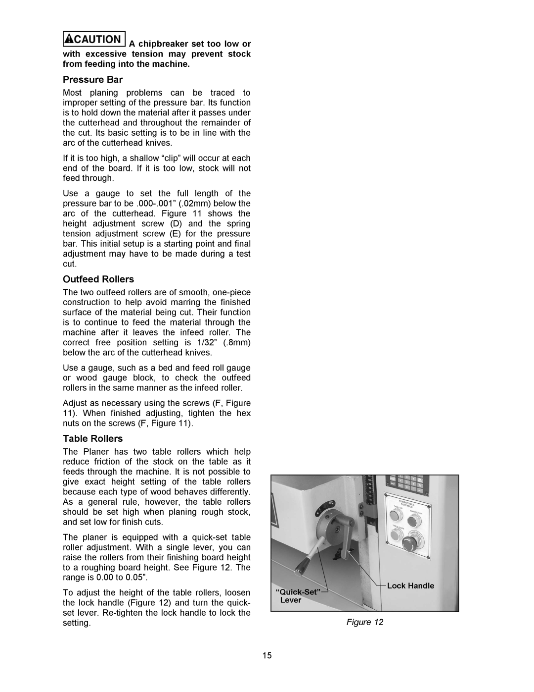
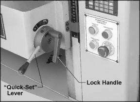
The planer is equipped with a
To adjust the height of the table rollers, loosen |
|
the lock handle (Figure 12) and turn the quick- |
|
set lever. | Figure 12 |
setting. |
15