Feed restriction can also occur due to pitch buildup on the table. Be sure the table surface is clean. Dusting the surface with talc occasionally will aid in smoother feeding and help prevent pitch buildup.
Clip Marks
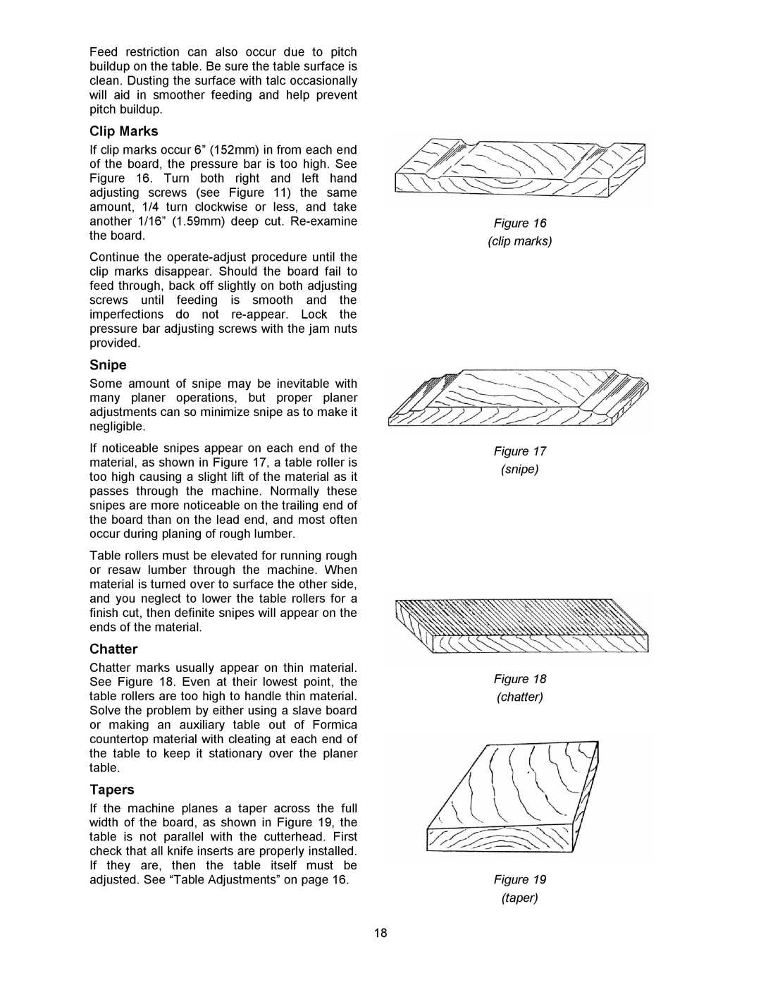
If clip marks occur 6” (152mm) in from each end of the board, the pressure bar is too high. See Figure 16. Turn both right and left hand adjusting screws (see Figure 11) the same amount, 1/4 turn clockwise or less, and take another 1/16” (1.59mm) deep cut.
Continue the
Snipe
Some amount of snipe may be inevitable with many planer operations, but proper planer adjustments can so minimize snipe as to make it negligible.
If noticeable snipes appear on each end of the material, as shown in Figure 17, a table roller is too high causing a slight lift of the material as it passes through the machine. Normally these snipes are more noticeable on the trailing end of the board than on the lead end, and most often occur during planing of rough lumber.
Table rollers must be elevated for running rough or resaw lumber through the machine. When material is turned over to surface the other side, and you neglect to lower the table rollers for a finish cut, then definite snipes will appear on the ends of the material.
Chatter
Chatter marks usually appear on thin material. See Figure 18. Even at their lowest point, the table rollers are too high to handle thin material. Solve the problem by either using a slave board or making an auxiliary table out of Formica countertop material with cleating at each end of the table to keep it stationary over the planer table.
Tapers
If the machine planes a taper across the full width of the board, as shown in Figure 19, the table is not parallel with the cutterhead. First check that all knife inserts are properly installed. If they are, then the table itself must be adjusted. See “Table Adjustments” on page 16.
Figure 16
(clip marks)
Figure 17 (snipe)
Figure 18
(chatter)
Figure 19 (taper)
18