Powerware Powerware 9390 manual 164201546---4

Models: Powerware 9390

1 124
Download 124 pages 14.91 Kb
Page 70
Image 70

INSTALLATION INFORMATION

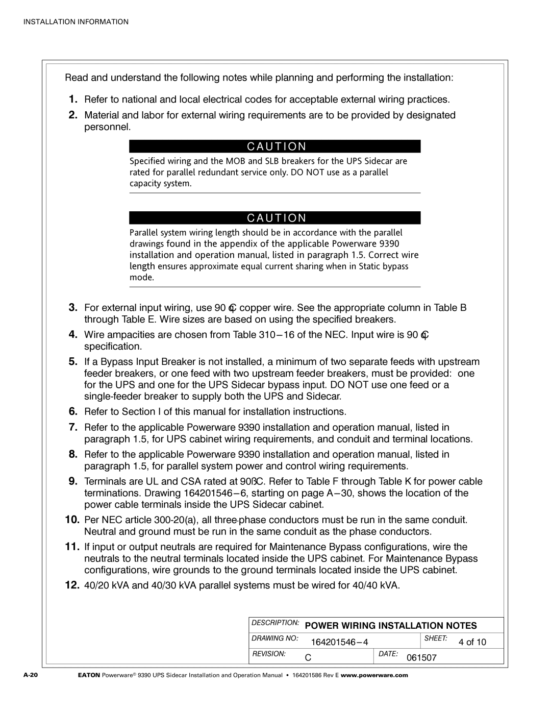
Read and understand the following notes while planning and performing the installation:

1.Refer to national and local electrical codes for acceptable external wiring practices.

2.Material and labor for external wiring requirements are to be provided by designated personnel.

C A U T I O N

Specified wiring and the MOB and SLB breakers for the UPS Sidecar are rated for parallel redundant service only. DO NOT use as a parallel capacity system.

C A U T I O N

Parallel system wiring length should be in accordance with the parallel drawings found in the appendix of the applicable Powerware 9390 installation and operation manual, listed in paragraph 1.5. Correct wire length ensures approximate equal current sharing when in Static bypass mode.

3.For external input wiring, use 90°C copper wire. See the appropriate column in Table B through Table E. Wire sizes are based on using the specified breakers.

4.Wire ampacities are chosen from Table 310---16 of the NEC. Input wire is 90°C specification.

5.If a Bypass Input Breaker is not installed, a minimum of two separate feeds with upstream feeder breakers, or one feed with two upstream feeder breakers, must be provided: one for the UPS and one for the UPS Sidecar bypass input. DO NOT use one feed or a single-feeder breaker to supply both the UPS and Sidecar.

6.Refer to Section I of this manual for installation instructions.

7.Refer to the applicable Powerware 9390 installation and operation manual, listed in paragraph 1.5, for UPS cabinet wiring requirements, and conduit and terminal locations.

8.Refer to the applicable Powerware 9390 installation and operation manual, listed in paragraph 1.5, for parallel system power and control wiring requirements.

9.Terminals are UL and CSA rated at 90˚C. Refer to Table F through Table K for power cable terminations. Drawing 164201546---6, starting on page A---30, shows the location of the power cable terminals inside the UPS Sidecar cabinet.

10.Per NEC article 300-20(a), all three-phase conductors must be run in the same conduit. Neutral and ground must be run in the same conduit as the phase conductors.

11.If input or output neutrals are required for Maintenance Bypass configurations, wire the neutrals to the neutral terminals located inside the UPS cabinet. For Maintenance Bypass configurations, wire grounds to the ground terminals located inside the UPS cabinet.

12.40/20 kVA and 40/30 kVA parallel systems must be wired for 40/40 kVA.

DESCRIPTION: POWER WIRING INSTALLATION NOTES


DRAWING NO:

164201546---4


SHEET:

4 of 10


REVISION:

C

DATE: 061507


A-20

EATON Powerware® 9390 UPS Sidecar Installation and Operation Manual S 164201586 Rev E www.powerware.com

Page 70
Image 70
Powerware Powerware 9390 manual 164201546---4

Powerware 9390 specifications

The Powerware 9390 is a high-performance uninterruptible power supply (UPS) that has been designed for mission-critical applications, providing reliable power protection and ensuring the continuous operation of sensitive equipment. It is particularly well-suited for data centers, telecommunications, and healthcare environments, where power reliability is paramount.

One of the standout features of the Powerware 9390 is its impressive scalability. This UPS is available in various capacities, typically ranging from 80 kVA to 500 kVA, allowing organizations to select a model that perfectly aligns with their power requirements. The modular design of the Powerware 9390 enables users to expand their system easily, accommodating future growth without significant investments in new equipment.

Another significant characteristic of the Powerware 9390 is its high efficiency. The UPS is equipped with advanced technologies that deliver exceptional energy efficiency, often exceeding 94% during normal operating conditions. This high efficiency not only reduces operational costs but also minimizes the carbon footprint of organizations, making the Powerware 9390 an environmentally friendly choice.

The unit offers advanced digital signal processing (DSP) technology, enhancing the unit's performance and ensuring that it can handle varying load conditions effectively. The Powerware 9390 is designed to provide a high level of protection against power disturbances and outages, including voltage sags, surges, and frequency variations.

The Powerware 9390 incorporates a user-friendly interface, featuring an intuitive LCD display that provides real-time information on system status, operational parameters, and alarms. This transparency allows facility managers to monitor the UPS at a glance and take necessary actions when required.

Additionally, for enhanced reliability, the Powerware 9390 supports a hot-swappable battery configuration. This feature is particularly beneficial as it enables battery replacement without disrupting the power supply, thus maintaining continuous operation during maintenance.

Moreover, the UPS supports various communication protocols, allowing integration with building management systems and enabling remote monitoring capabilities. This feature is crucial for operators who need to keep a constant eye on power conditions and ensure optimal performance.

In summary, the Powerware 9390 stands out as a robust, efficient, and scalable UPS solution. Its advanced technologies and features cater to the power protection needs of critical applications, making it an ideal choice for organizations that demand reliability and efficiency in their power systems. With its combination of scalability, energy efficiency, user-friendly interface, and robust protection capabilities, the Powerware 9390 continues to be a preferred solution for many industries worldwide.