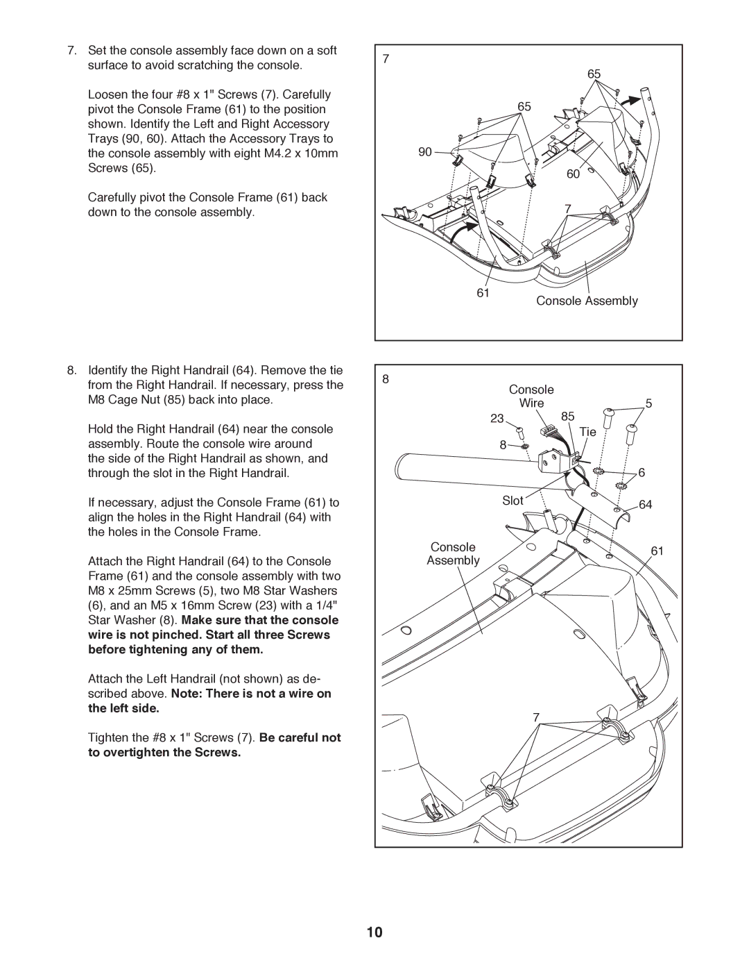
7. Set the console assembly face down on a soft | 7 |
|
|
|
surface to avoid scratching the console. |
|
| 65 | |
|
|
| ||
|
|
|
| |
Loosen the four #8 x 1" Screws (7). Carefully |
|
| 65 |
|
pivot the Console Frame (61) to the position |
|
|
| |
shown. Identify the Left and Right Accessory |
|
|
|
|
Trays (90, 60). Attach the Accessory Trays to |
| 90 |
|
|
the console assembly with eight M4.2 x 10mm |
|
|
| |
Screws (65). |
|
|
| 60 |
|
|
|
| |
Carefully pivot the Console Frame (61) back |
|
|
| 7 |
down to the console assembly. |
|
|
| |
|
| 61 | Console Assembly | |
|
|
| ||
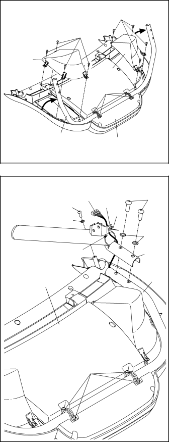
8. Identify the Right Handrail (64). Remove the tie | 8 |
|
|
|
from the Right Handrail. If necessary, press the |
| Console |
| |
|
| 5 | ||
M8 Cage Nut (85) back into place. |
|
| Wire | |
Hold the Right Handrail (64) near the console |
|
| 23 | 85 |
|
| 8 | Tie | |
assembly. Route the console wire around |
|
|
| |
the side of the Right Handrail as shown, and |
|
|
| 6 |
through the slot in the Right Handrail. |
|
|
| |
If necessary, adjust the Console Frame (61) to |
|
| Slot | 64 |
align the holes in the Right Handrail (64) with |
|
|
|
|
the holes in the Console Frame. |
| Console |
| 61 |
Attach the Right Handrail (64) to the Console |
|
| ||
| Assembly |
|
| |
Frame (61) and the console assembly with two |
|
|
|
|
M8 x 25mm Screws (5), two M8 Star Washers |
|
|
|
|
(6), and an M5 x 16mm Screw (23) with a 1/4" |
|
|
|
|
Star Washer (8). Make sure that the console |
|
|
|
|
wire is not pinched. Start all three Screws |
|
|
|
|
before tightening any of them. |
|
|
|
|
Attach the Left Handrail (not shown) as de- |
|
|
|
|
scribed above. Note: There is not a wire on |
|
|
|
|
the left side. |
|
| 7 |
|
Tighten the #8 x 1" Screws (7). Be careful not |
|
|
| |
|
|
|
| |
to overtighten the Screws. |
|
|
|
|
| 10 |
|
|
|