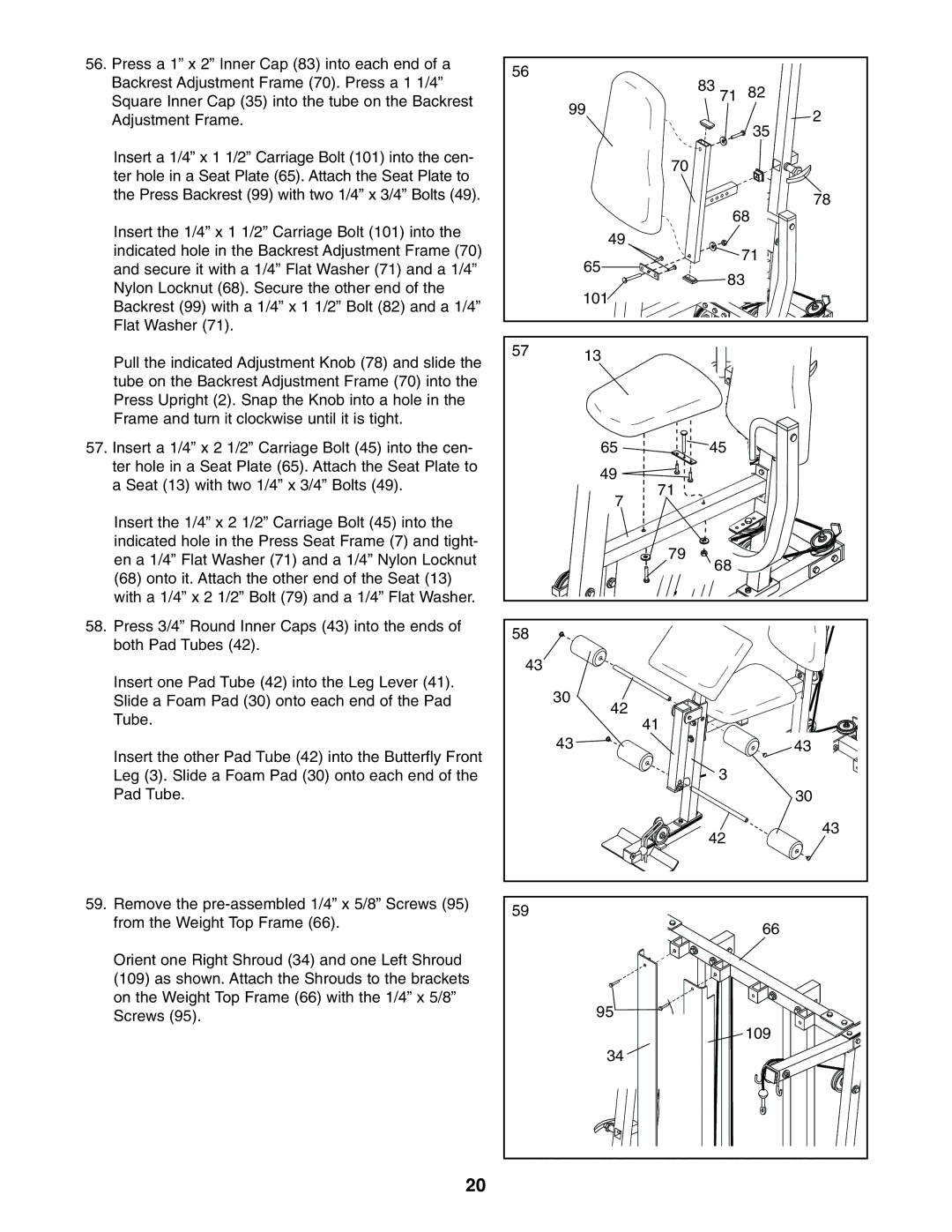
56. Press a 1” x 2” Inner Cap (83) into each end of a | 56 |
|
|
|
Backrest Adjustment Frame (70). Press a 1 1/4” |
| 83 71 |
| |
|
| 82 | ||
Square Inner Cap (35) into the tube on the Backrest |
| 99 | ||
|
| 2 | ||
Adjustment Frame. |
|
| ||
|
|
| ||
|
|
|
| 35 |
Insert a 1/4” x 1 1/2” Carriage Bolt (101) into the cen- |
|
| 70 |
|
ter hole in a Seat Plate (65). Attach the Seat Plate to |
|
|
| |
|
|
|
| |
the Press Backrest (99) with two 1/4” x 3/4” Bolts (49). |
|
|
| 78 |
|
|
|
| |
Insert the 1/4” x 1 1/2” Carriage Bolt (101) into the |
|
| 68 | |
| 49 |
|
| |
indicated hole in the Backrest Adjustment Frame (70) |
|
| 71 | |
| 65 |
| ||
and secure it with a 1/4” Flat Washer (71) and a 1/4” |
|
| ||
| 83 | |||
Nylon Locknut (68). Secure the other end of the |
|
| ||
| 101 |
|
| |
Backrest (99) with a 1/4” x 1 1/2” Bolt (82) and a 1/4” |
|
|
| |
|
|
|
| |
Flat Washer (71). |
|
|
|
|
Pull the indicated Adjustment Knob (78) and slide the | 57 | 13 |
|
|
|
|
| ||
|
|
|
| |
tube on the Backrest Adjustment Frame (70) into the |
|
|
|
|
Press Upright (2). Snap the Knob into a hole in the |
|
|
|
|
Frame and turn it clockwise until it is tight. |
|
|
|
|
57. Insert a 1/4” x 2 1/2” Carriage Bolt (45) into the cen- |
| 65 | 45 |
|
ter hole in a Seat Plate (65). Attach the Seat Plate to |
| 49 |
|
|
a Seat (13) with two 1/4” x 3/4” Bolts (49). |
| 71 |
| |
| 7 |
| ||
|
|
| ||
|
|
|
| |
Insert the 1/4” x 2 1/2” Carriage Bolt (45) into the |
|
|
|
|
indicated hole in the Press Seat Frame (7) and tight- |
|
| 79 |
|
en a 1/4” Flat Washer (71) and a 1/4” Nylon Locknut |
|
|
| |
|
| 68 |
| |
(68) onto it. Attach the other end of the Seat (13) |
|
|
| |
|
|
|
| |
with a 1/4” x 2 1/2” Bolt (79) and a 1/4” Flat Washer. |
|
|
|
|
58. Press 3/4” Round Inner Caps (43) into the ends of | 58 |
|
|
|
both Pad Tubes (42). |
|
|
| |
|
|
|
| |
Insert one Pad Tube (42) into the Leg Lever (41). | 43 |
|
|
|
| 30 |
|
| |
Slide a Foam Pad (30) onto each end of the Pad |
|
|
| |
Tube. |
| 42 | 41 |
|
|
|
| ||
|
|
|
| |
Insert the other Pad Tube (42) into the Butterfly Front |
| 43 |
| 43 |
|
| 3 |
| |
Leg (3). Slide a Foam Pad (30) onto each end of the |
|
|
| |
Pad Tube. |
|
|
| 30 |
|
|
| 42 | 43 |
|
|
|
| |
59. Remove the | 59 |
|
|
|
from the Weight Top Frame (66). |
|
|
| |
|
|
| 66 | |
|
|
|
| |
Orient one Right Shroud (34) and one Left Shroud |
|
|
|
|
(109) as shown. Attach the Shrouds to the brackets |
|
|
|
|
on the Weight Top Frame (66) with the 1/4” x 5/8” |
| 95 |
|
|
Screws (95). |
|
| 109 | |
|
|
|
| |
|
| 34 |
|
|
20
