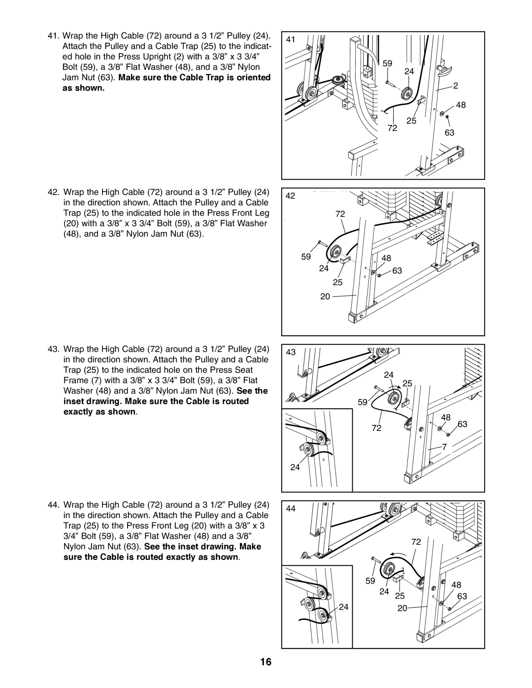
41.Wrap the High Cable (72) around a 3 1/2” Pulley (24). Attach the Pulley and a Cable Trap (25) to the indicat- ed hole in the Press Upright (2) with a 3/8” x 3 3/4” Bolt (59), a 3/8” Flat Washer (48), and a 3/8” Nylon Jam Nut (63). Make sure the Cable Trap is oriented as shown.
42.Wrap the High Cable (72) around a 3 1/2” Pulley (24) in the direction shown. Attach the Pulley and a Cable Trap (25) to the indicated hole in the Press Front Leg (20) with a 3/8” x 3 3/4” Bolt (59), a 3/8” Flat Washer (48), and a 3/8” Nylon Jam Nut (63).
43.Wrap the High Cable (72) around a 3 1/2” Pulley (24) in the direction shown. Attach the Pulley and a Cable Trap (25) to the indicated hole on the Press Seat Frame (7) with a 3/8” x 3 3/4” Bolt (59), a 3/8” Flat Washer (48) and a 3/8” Nylon Jam Nut (63). See the inset drawing. Make sure the Cable is routed exactly as shown.
44.Wrap the High Cable (72) around a 3 1/2” Pulley (24) in the direction shown. Attach the Pulley and a Cable Trap (25) to the Press Front Leg (20) with a 3/8” x 3 3/4” Bolt (59), a 3/8” Flat Washer (48) and a 3/8” Nylon Jam Nut (63). See the inset drawing. Make sure the Cable is routed exactly as shown.
41 |
|
|
|
| 59 | 24 |
|
|
|
| |
|
|
| 2 |
|
|
| 48 |
|
| 25 |
|
| 72 | 63 | |
|
|
| |
42 |
|
|
|
72 |
|
|
|
59 | 48 |
|
|
24 |
| 63 |
|
25 |
|
|
|
20 |
|
|
|
43 |
|
|
|
| 24 |
| |
|
| 25 |
|
| 59 |
|
|
|
|
| 48 |
| 72 |
| 63 |
|
|
| |
|
|
| 7 |
24 |
|
|
|
44 |
|
|
|
|
| 72 |
|
| 59 |
| 48 |
| 24 |
| |
| 25 | 63 | |
24 |
| 20 |
|
16
