INSTALLATION AND | CHAPTER 2 |
CONNECTION |
|
Please note that it is important to keep in mind common safety guidelines when installing your DVR or connecting additional devices – including turning off and unplugging your DVR before installing internal components.
2.1 DVR INSTALLATION
This DVR can be mounted on the included stand or it can be
To attach the circular base to the DVR, use the five included screws.
PICTURE
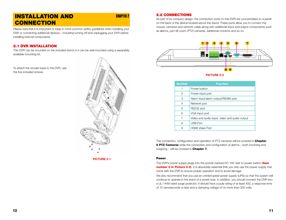
2.2 CONNECTIONS
As part of its compact design, the connection ports on this DVR are concentrated on a panel on the back of the device located above the stand. These ports allow you to connect the mouse, cameras and network cable along with additional input and output components such as alarms,
|
|
|
|
|
|
|
|
|
|
|
|
|
1 | 2 | 3 | 4 | 5 | 6 | 7 |
|
|
|
|
|
|
|
|
|
| RS232 |
|
|
DC 19V |
|
|
|
|
|
|
|
| NET |
|
|
|
|
|
|
|
|
|
|
|
| USB | HDMI | VGA | AUDIO/VIDEO |
| 1 |
|
| 2 |
| CNTRL |
| A | B |
|
|
|
NO | C |
| NO | C |
| 12V |
|
|
|
| ||
1 | 2 | 3 | 4 |
| 5 | 6 | 7 | 8 |
|
|
|
|
8 9
PICTURE
Number | Function |
1Power button
2Power input port
3Alarm input/alarm output/RS485 port
4Network port
5RS232 port
6VGA input port
7Video and audio input, video and audio output
8USB Port
9HDMI Video Port
The connection, configuration and operation of PTZ cameras | will be | covered in Chapter |
6 PTZ Cameras while the connection and configuration of | alarms – | both incoming and |
outgoing – will be covered in Chapter 7. |
|
|
Power
The DVR’s power supply plugs into the socket marked DC 19V next to power switch (Item number 2 in Picture
We also recommend that you use an uninterrupted power supply (UPS) so that the system will continue to operate in the event of a power loss. In addition, you should connect the DVR into a
10 | 11 |