PAN/TILT/ZOOM CAMERAS | CHAPTER 6 |
6.1 CONNECTING A PTZ CAMERA
The RS485 connector is used to connect and control PTZ cameras. It uses a
The DVR is set by default for RS485 to be disabled for each channel. Therefore, PTZ settings must be enabled before PTZ cameras can be utilized. This system supports 26 of the most common protocols including
When connecting a PTZ camera, the following should be taken into account:
• Ensure that the camera has the same grounding with the DVR otherwise you may not be |
able to control the PTZ. Shielded twisted wire is recommended with the shielded layer being |
used to connect to the ground. Improper grounding may result in chip damage. |
• For excessively long wire runs, or if multiple PTZ cameras are connected to the DVR, 120Ω |
should be parallel connected between the A and B lines on the far end to reduce reflection |
6.2 PTZ CONTROL AND SETUP
The following instructions are based on the
SETUP
For ease of
STEP 1. Open the Pan/Tilt/Zoom Menu from the Settings menu. You cannot use the Shortcut Menu to access the PTZ controls until after you have configured a channel to use PTZ.
and maintain the signal quality |
• The 485 port of this DVR cannot parallel connect with the 485 port of another device |
• The voltage between the A and B lines of the camera should be less than 5V. |
STEP 2. Be certain that the channel
PICTURE
CHAPTER 6![]()
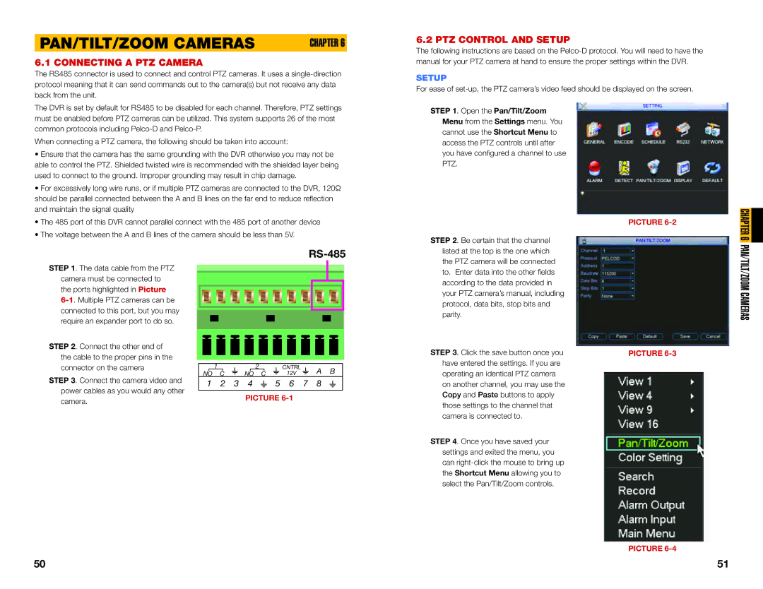
STEP 1. The data cable from the PTZ camera must be connected to the ports highlighted in Picture
STEP 2. Connect the other end of the cable to the proper pins in the connector on the camera
STEP 3. Connect the camera video and power cables as you would any other camera.
RS-485
| 1 |
|
|
|
| 2 |
|
|
|
|
|
| CNTRL |
|
|
|
|
| A B | |
NO C |
|
|
| NO C |
|
|
|
|
| 12V |
|
|
|
|
| |||||
1 2 3 4  5 6 7 8
PICTURE
listed at the top is the one which the PTZ camera will be connected to. Enter data into the other fields according to the data provided in your PTZ camera’s manual, including protocol, data bits, stop bits and parity.
STEP 3. Click the save button once you have entered the settings. If you are operating an identical PTZ camera on another channel, you may use the Copy and Paste buttons to apply those settings to the channel that camera is connected to.
STEP 4. Once you have saved your settings and exited the menu, you can
PICTURE
PAN/TILT/ZOOM CAMERAS
PICTURE
50 | 51 |