XCLK
RTS
CTS
RCLK DTR DSR DCD RI
|
|
|
|
| AUXOUT | |
|
|
|
|
|
| |
|
|
|
|
|
| Driver |
4 | 5 | 6 |
|
|
| TXEN |
1 | 2 | 3 | 4 | 5 | 6 | |
|
|
| ||||
|
|
| 1 | 2 | 3 |
|
|
|
|
|
| AUXIN | |
|
|
|
|
| ||
|
|
|
|
|
| Receiver |
|
|
|
|
|
| RXEN |
+
-
+
-
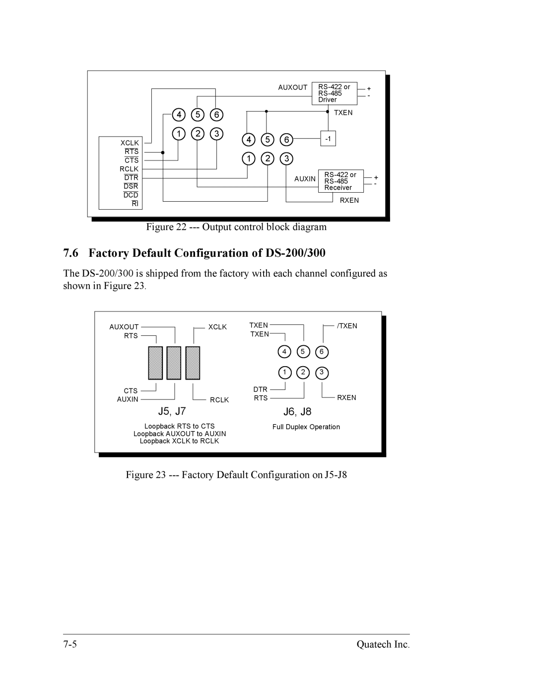
Figure 22 --- Output control block diagram
7.6 Factory Default Configuration of DS-200/300
The
AUXOUT RTS
XCLK TXEN TXEN ![]()
![]()
![]() /TXEN
/TXEN
5 | 6 |
1 | 2 |
CTS
AUXIN
7 |
3 |
| 4 | 5 | 6 |
| 1 | 2 | 3 |
| DTR |
| RXEN |
RCLK | RTS |
|
J5, J7 | J6, J8 |
Loopback RTS to CTS | Full Duplex Operation |
Loopback AUXOUT to AUXIN |
|
Loopback XCLK to RCLK |
|
|
|
|
|
Figure 23 --- Factory Default Configuration on J5-J8
Quatech Inc. |