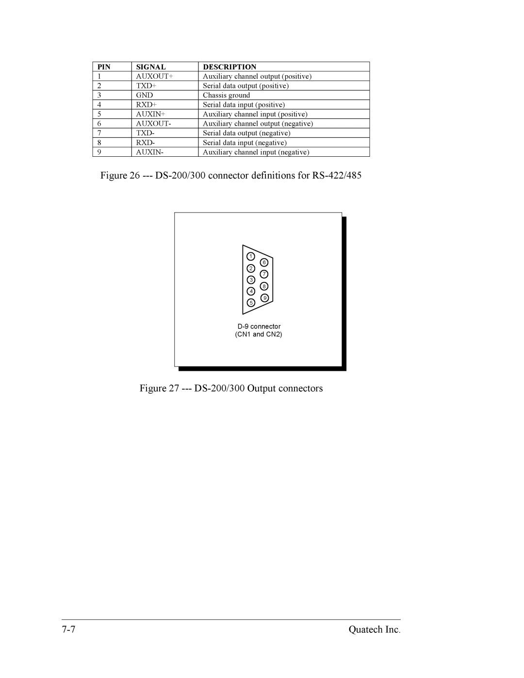
PIN | SIGNAL | DESCRIPTION |
1 | AUXOUT+ | Auxiliary channel output (positive) |
2 | TXD+ | Serial data output (positive) |
3 | GND | Chassis ground |
4 | RXD+ | Serial data input (positive) |
5 | AUXIN+ | Auxiliary channel input (positive) |
6 | AUXOUT- | Auxiliary channel output (negative) |
7 | TXD- | Serial data output (negative) |
8 | RXD- | Serial data input (negative) |
9 | AUXIN- | Auxiliary channel input (negative) |
Figure 26 --- DS-200/300 connector definitions for RS-422/485
1
6
2
7
3
8
4
9
5
Figure 27 --- DS-200/300 Output connectors
Quatech Inc. |
