VOYAGEUR GRAND Wood Insert
R
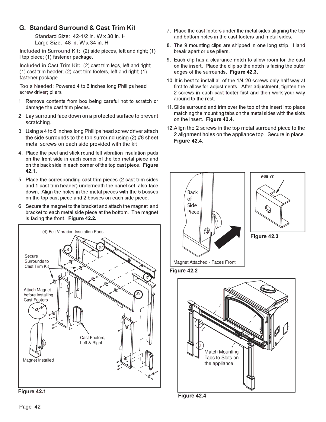
G. Standard Surround & Cast Trim Kit | 7. Place the cast footers under the metal sides aligning the top | ||||
Standard Size: |
| and bottom holes in the cast footers and metal sides. | |||
Large Size: 48 in. W x 34 in. H | 8. The 9 mounting clips are shipped in one long strip. Hand | ||||
Included in Surround Kit: (2) side pieces, left and right; (1) | |||||
| break apart or use pliers. | ||||
l top piece; (1) fastener package. | 9. Each clip has a clearance notch to allow room for the cast | ||||
Included in Cast Trim Kit: (2) cast trim legs, left and right; | |||||
| on the insert. Place the clip so the notch is facing the outer | ||||
(1) cast trim header; (2) cast trim footers, left and right; (1) |
| edges of the surrounds. Figure 42.3. | |||
fastener package. | 10. It is best to install all of the | ||||
Tools Needed: Powered 4 to 6 inches long Phillips head | |||||
| first to allow for adjustments. After adjustment, tighten the | ||||
screw driver; pliers |
| 2 screws in each cast footer first and then work your way | |||
1. Remove contents from box being careful not to scratch or |
| around to the rest. | |||
11. Slide surround and trim over the top of the insert into place | |||||
damage the cast trim pieces. | |||||
2. Lay surround face down on a protected surface to prevent |
| matching the mounting tabs on the metal sides with the slots | |||
| on the insert. Figure 42.4. | ||||
scratching. |
| ||||
12.Align the 2 screws in the top metal surround piece to the | |||||
3. Using a 4 to 6 inches long Phillips head screw driver attach | |||||
| 2 alignment holes on the appliance top. Secure in place. | ||||
the side surrounds to the top surround using (2) #8 sheet |
| ||||
| Figure 42.4. | ||||
metal screws on each side provided with the kit |
| ||||
|
|
|
| ||
4. Place the peel and stick round felt vibration insulation pads |
|
|
|
| |
on the front side in each corner of the top metal piece and |
|
|
|
| |
on the back side in each corner of the top cast piece. Figure |
|
|
|
| |
42.1. |
|
|
|
| |
|
|
| Clearance Notch | ||
5. Place the corresponding cast trim pieces (2 cast trim sides |
|
|
| ||
|
|
|
| ||
and 1 cast trim header) underneath the panel set, also face |
|
|
|
| |
down. Align the holes in the metal pieces with the 5 bosses |
| Back | |||
on the top cast piece and 2 bosses on each side piece. |
| of | |||
6. Secure the magnet to the bracket and attach the magnet and |
| Side | |||
bracket to each metal side piece at the bottom. The magnet |
| Piece | |||
is facing the front. Figure 42.2. |
|
|
|
| |
(4) Felt Vibration Insulation Pads |
| Figure 42.3 |
|
| |
Secure |
|
|
Surrounds to | Magnet Attached - Faces Front |
|
Cast Trim Kit | Figure 42.2 |
|
|
| |
Attach Magnet |
|
|
before installing |
|
|
Cast Footers |
|
|
Cast Footers, |
|
|
Left & Right |
|
|
| Match Mounting |
|
Magnet Installed | Tabs to Slots on |
|
the appliance |
| |
|
| |
Figure 42.1 | Figure 42.4 |
|
|
| |
Page 42 | September 25, 2012 |