
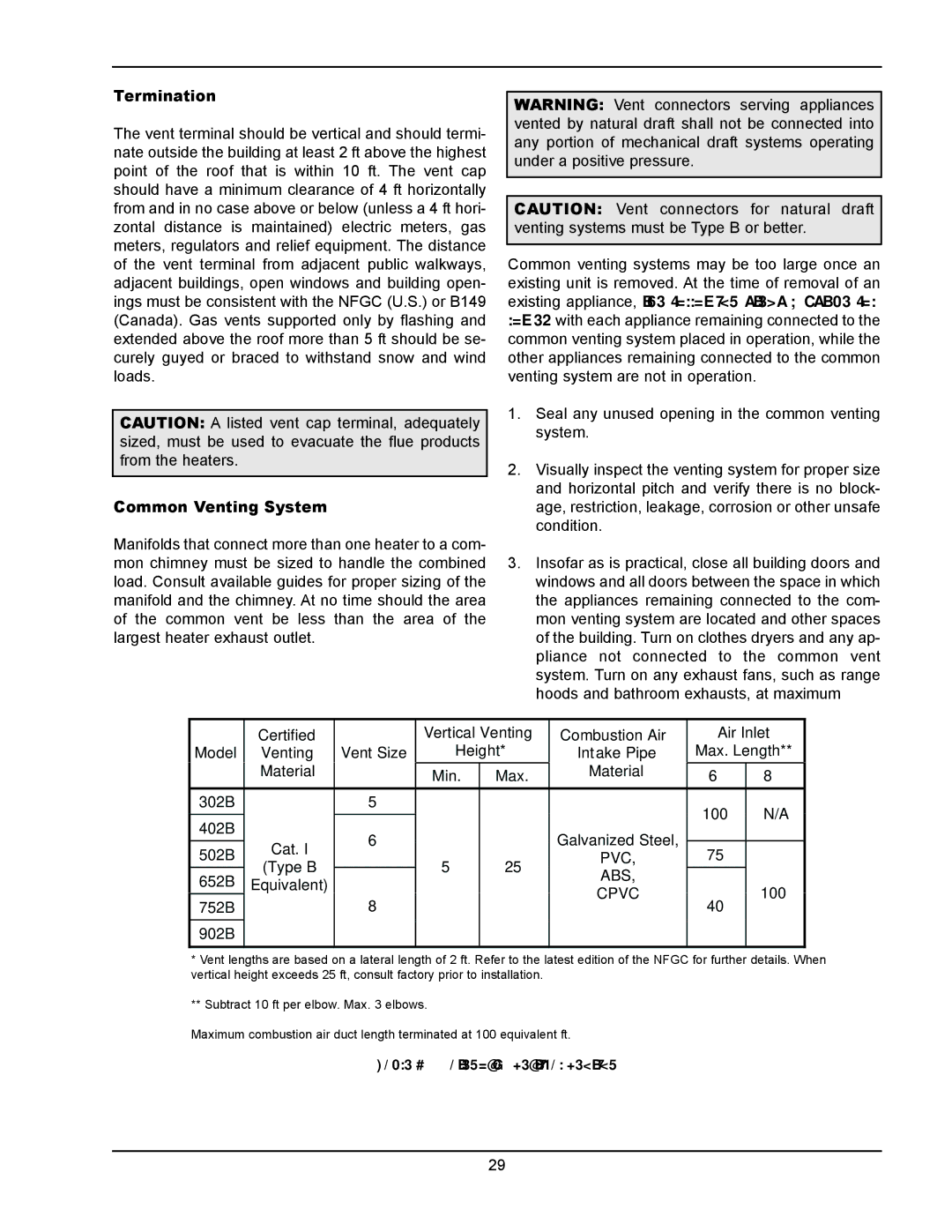
302B, 902B specifications
Raypak is a prominent name in the heating industry, particularly known for its advanced technology and robust design in residential and commercial heating solutions. Two of their notable models, the Raypak 302B and 402B, exemplify innovation and efficiency in hydronic heating systems, designed to meet diverse needs while ensuring optimal performance.The Raypak 302B and 402B are high-efficiency boilers that utilize gas-fueled systems. The 302B model has a heating capacity of 302,000 BTU/h, while the 402B boasts a maximum capacity of 402,000 BTU/h. This range of heating output makes these models suitable for a variety of applications, from residential heating needs to larger commercial spaces that require a reliable heat source.
One of the standout features of the Raypak 302B and 402B is their use of fire-tube heat exchanger technology. This design promotes efficient heat transfer and allows for lower emissions, thus minimizing the environmental impact. The fire-tube design also contributes to a longer lifespan and reduced maintenance costs, making these boilers a cost-effective solution over time.
Equipped with advanced control systems, the Raypak 302B and 402B ensure precise temperature regulation and improved energy usage. The digital display provides real-time feedback and diagnostics, enhancing user experience and simplifying troubleshooting. These models are also compatible with various building management systems, providing users with versatility in integration to optimize building performance.
In addition to their technological advancements, these boilers are designed with user safety and convenience in mind. They include features such as built-in safety controls, easy access for service and maintenance, and a compact footprint to fit into tight spaces. Their robust construction ensures durability, which is crucial for systems that operate under high demand.
Moreover, both models have been engineered to succeed in various climates, making them reliable choices for users in diverse geographical locations. With their energy-efficient operation, reliable performance, and advanced features, the Raypak 302B and 402B embody quality and innovation in the heating market, ensuring comfortable environments while lowering energy costs and environmental footprints.