Gas Supply

DANGER: Make sure the gas on which the heater will operate is the same type as specified on the heater’s rating plate.

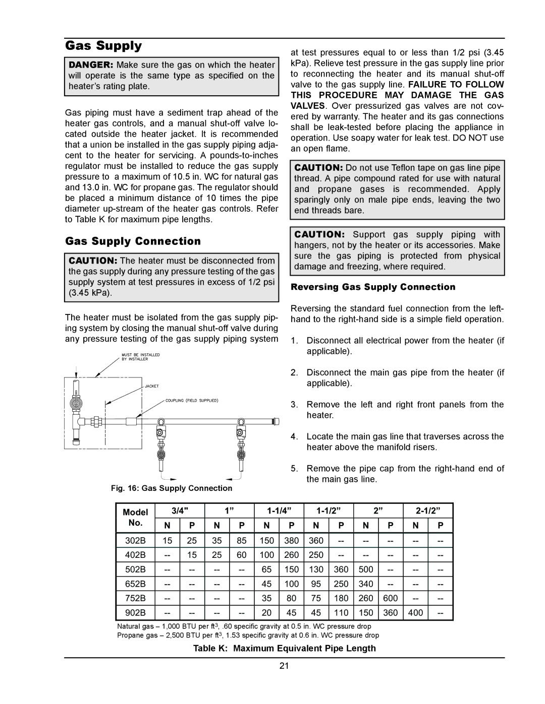
Gas piping must have a sediment trap ahead of the heater gas controls, and a manual shut-off valve lo- cated outside the heater jacket. It is recommended that a union be installed in the gas supply piping adja- cent to the heater for servicing. A pounds-to-inches regulator must be installed to reduce the gas supply pressure to a maximum of 10.5 in. WC for natural gas and 13.0 in. WC for propane gas. The regulator should be placed a minimum distance of 10 times the pipe diameter up-stream of the heater gas controls. Refer to Table K for maximum pipe lengths.

Gas Supply Connection

CAUTION: The heater must be disconnected from the gas supply during any pressure testing of the gas supply system at test pressures in excess of 1/2 psi (3.45 kPa).

The heater must be isolated from the gas supply pip- ing system by closing the manual shut-off valve during any pressure testing of the gas supply piping system

Fig. 16: Gas Supply Connection

at test pressures equal to or less than 1/2 psi (3.45 kPa). Relieve test pressure in the gas supply line prior to reconnecting the heater and its manual shut-off valve to the gas supply line. FAILURE TO FOLLOW

THIS PROCEDURE MAY DAMAGE THE GAS VALVES. Over pressurized gas valves are not cov- ered by warranty. The heater and its gas connections shall be leak-tested before placing the appliance in operation. Use soapy water for leak test. DO NOT use an open flame.

CAUTION: Do not use Teflon tape on gas line pipe thread. A pipe compound rated for use with natural and propane gases is recommended. Apply sparingly only on male pipe ends, leaving the two end threads bare.

CAUTION: Support gas supply piping with hangers, not by the heater or its accessories. Make sure the gas piping is protected from physical damage and freezing, where required.

Reversing Gas Supply Connection

Reversing the standard fuel connection from the left- hand to the right-hand side is a simple field operation.

1.Disconnect all electrical power from the heater (if applicable).

2.Disconnect the main gas pipe from the heater (if applicable).

3.Remove the left and right front panels from the heater.

4.Locate the main gas line that traverses across the heater above the manifold risers.

5.Remove the pipe cap from the right-hand end of the main gas line.

Model

No.

3/4"


1”

1-1/4”

1-1/2”


2”

2-1/2”


N

P

N


P

N

P

N

P

N


P

N

P


302B

15

25

35

85

150

380

360

--

--

--

--

--


402B

--

15

25

60

100

260

250

--

--

--

--

--


502B

--

--

--

--

65

150

130

360

500

--

--

--


652B

--

--

--

--

45

100

95

250

340

--

--

--


752B

--

--

--

--

35

80

75

180

260

600

--

--


902B

--

--

--

--

20

45

45

110

150

360

400

--


Natural gas – 1,000 BTU per ft3, .60 specific gravity at 0.5 in. WC pressure drop Propane gas – 2,500 BTU per ft3, 1.53 specific gravity at 0.6 in. WC pressure drop

Table K: Maximum Equivalent Pipe Length

21

Page 21
Image 21
Raypak 302B, 902B manual Gas Supply Connection, Model, Table K Maximum Equivalent Pipe Length

302B, 902B specifications

Raypak is a prominent name in the heating industry, particularly known for its advanced technology and robust design in residential and commercial heating solutions. Two of their notable models, the Raypak 302B and 402B, exemplify innovation and efficiency in hydronic heating systems, designed to meet diverse needs while ensuring optimal performance.

The Raypak 302B and 402B are high-efficiency boilers that utilize gas-fueled systems. The 302B model has a heating capacity of 302,000 BTU/h, while the 402B boasts a maximum capacity of 402,000 BTU/h. This range of heating output makes these models suitable for a variety of applications, from residential heating needs to larger commercial spaces that require a reliable heat source.

One of the standout features of the Raypak 302B and 402B is their use of fire-tube heat exchanger technology. This design promotes efficient heat transfer and allows for lower emissions, thus minimizing the environmental impact. The fire-tube design also contributes to a longer lifespan and reduced maintenance costs, making these boilers a cost-effective solution over time.

Equipped with advanced control systems, the Raypak 302B and 402B ensure precise temperature regulation and improved energy usage. The digital display provides real-time feedback and diagnostics, enhancing user experience and simplifying troubleshooting. These models are also compatible with various building management systems, providing users with versatility in integration to optimize building performance.

In addition to their technological advancements, these boilers are designed with user safety and convenience in mind. They include features such as built-in safety controls, easy access for service and maintenance, and a compact footprint to fit into tight spaces. Their robust construction ensures durability, which is crucial for systems that operate under high demand.

Moreover, both models have been engineered to succeed in various climates, making them reliable choices for users in diverse geographical locations. With their energy-efficient operation, reliable performance, and advanced features, the Raypak 302B and 402B embody quality and innovation in the heating market, ensuring comfortable environments while lowering energy costs and environmental footprints.