Preparation

WARNING: Do not turn on gas at this time.

Check Power Supply

With multi-meter at incoming power, check voltage between:

Hot - Common (≈120 VAC)

Hot - Ground (≈120 VAC)

Common - Ground (< 1 VAC)

WARNING: If Common - Ground is > 1 VAC,

STOP: Contact electrician to correct ground failure. Failure to do this may burn out 120V-24V transformer, or may cause other safety control damage or failure.

Attach Manometers to Measure Pressures

1.Turn off main gas valve.

2.Attach 24” scale manometer to the first main gas shut-off valve pressure tapping.

3.Attach (1) 12” scale manometer to the outlet side of the second main gas shut-off valve pressure tapping.

4.Attach (1) 12” scale manometer near the fan-prov- ing switch. Pull black cap from air pressure switch tee and connect the manometer. NOTE: Retain caps for reinstallation later.

Check Gas Supply Pressure

1.Slowly turn on main gas shut-off valve.

2.Read the gas supply pressure from the manome- ter; minimum supply pressure for natural gas is 5.0 in. WC, recommended supply is 7.0 in. WC, mini- mum supply pressure for propane gas is 11.0 in. WC (dynamic readings, all stages firing).

3.If the pressure is > 14.0 in. WC, turn off the valve.

4.Check if the service regulator is installed and/or adjust the service regulator.

Start-Up

Blower Adjustment

1.Turn off power.

2.Unplug cap at pressure switches and connect ma- nometer(s) to the tee.

3.Close all manual firing valves.

4.Turn power on.

5.Check manometers attached to fan pressure switch. The reading should be 1.4 ± .1 in. WC for propane gas and natural gas. If not, adjust the air shutter on the blowers to attain the correct value.

6.Turn power off.

7.Reconnect this cap.

Main Burner Adjustment

1.Turn off unit.

2.Open manual firing valves.

3.Turn on the unit, wait 15 seconds, and the igniter should glow. Look into sight glass located at each end of the heater to check igniter operation. Gas valves should open in 45-60 seconds.

4.If burner does not light on first trial. It will retry, up to three times.

5.Main burner ignition: Check manifold gas pressure at gas valve outlet pressure tap. This should read 3.5 ± 0.1 in. WC for natural gas and 10.5 ± 0.1 in. WC for propane gas.

6.If the pressure reading differs by more than ± 0.1 in. WC, remove screw cover from the gas pres- sure regulator and adjust main burner manifold pressure. Replace the screw cover. Repeat steps 2 to 5 on other valves as necessary.

CAUTION: Special manifold and air settings may be required. Verify rating plate and blower housing.

47

Page 47
Image 47
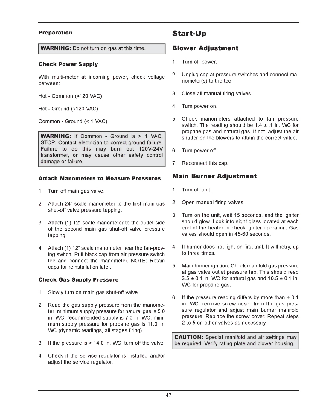
Raypak 302B, 902B manual Start-Up, Blower Adjustment, Main Burner Adjustment

302B, 902B specifications

Raypak is a prominent name in the heating industry, particularly known for its advanced technology and robust design in residential and commercial heating solutions. Two of their notable models, the Raypak 302B and 402B, exemplify innovation and efficiency in hydronic heating systems, designed to meet diverse needs while ensuring optimal performance.

The Raypak 302B and 402B are high-efficiency boilers that utilize gas-fueled systems. The 302B model has a heating capacity of 302,000 BTU/h, while the 402B boasts a maximum capacity of 402,000 BTU/h. This range of heating output makes these models suitable for a variety of applications, from residential heating needs to larger commercial spaces that require a reliable heat source.

One of the standout features of the Raypak 302B and 402B is their use of fire-tube heat exchanger technology. This design promotes efficient heat transfer and allows for lower emissions, thus minimizing the environmental impact. The fire-tube design also contributes to a longer lifespan and reduced maintenance costs, making these boilers a cost-effective solution over time.

Equipped with advanced control systems, the Raypak 302B and 402B ensure precise temperature regulation and improved energy usage. The digital display provides real-time feedback and diagnostics, enhancing user experience and simplifying troubleshooting. These models are also compatible with various building management systems, providing users with versatility in integration to optimize building performance.

In addition to their technological advancements, these boilers are designed with user safety and convenience in mind. They include features such as built-in safety controls, easy access for service and maintenance, and a compact footprint to fit into tight spaces. Their robust construction ensures durability, which is crucial for systems that operate under high demand.

Moreover, both models have been engineered to succeed in various climates, making them reliable choices for users in diverse geographical locations. With their energy-efficient operation, reliable performance, and advanced features, the Raypak 302B and 402B embody quality and innovation in the heating market, ensuring comfortable environments while lowering energy costs and environmental footprints.