Chapter 1: Connections and Setup
| INPUT | COMPONENT VIDEO OUT | OUTPUT |
| ||
|
|
|
|
| DIGITAL |
|
| VIDEO | Y |
|
| VIDEO AUDIO OUT | INPUT |
|
|
|
|
|
| |
| L |
| IN |
| L | CABLE/ANTENNA |
|
|
|
|
| ||
AC IN | Pb |
|
|
|
| |
|
| AUDIO |
|
| ||
| AUDIO |
|
| COAXIAL |
| |
|
|
|
|
| ||
PROG. |
| OUT |
|
|
| |
|
|
| R |
| ||
SCAN | R | Pr |
|
|
| |
|
|
| OUTPUT | |||
|
|
|
|
|
| |
OFF | ON |
|
|
| OPTICAL |
|
|
|
| CH3 | CH4 | ||
|
|
|
|
| ||
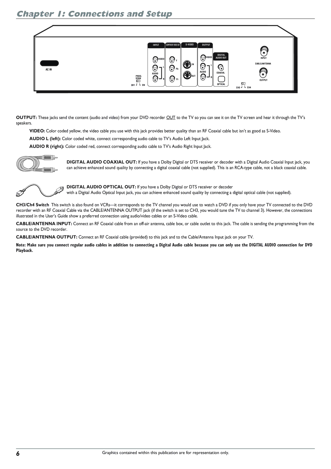
OUTPUT: These jacks send the content (audio and video) from your DVD recorder OUT to the TV so you can see it on the TV screen and hear it through the TV’s speakers.
VIDEO: Color coded yellow, the video cable you use with this jack provides better quality than an RF Coaxial cable but isn’t as good as
AUDIO L (left): Color coded white, connect corresponding audio cable to TV’s Audio Left Input Jack.
AUDIO R (right): Color coded red, connect corresponding audio cable to TV’s Audio Right Input Jack.
DIGITAL AUDIO COAXIAL OUT: If you have a Dolby Digital or DTS receiver or decoder with a Digital Audio Coaxial Input jack, you can achieve enhanced sound quality by connecting a digital coaxial cable (not supplied). This is an
DIGITAL AUDIO OPTICAL OUT: If you have a Dolby Digital or DTS receiver or decoder
with a Digital Audio Optical Input jack, you can achieve enhanced sound quality by connecting a digital optical cable (not supplied).
CH3/Ch4 Switch This switch is also found on
CABLE/ANTENNA INPUT: Connect an RF Coaxial cable from an
CABLE/ANTENNA OUTPUT: Connect an RF Coaxial cable (provided) to this jack and to the Cable/Antenna Input jack on your TV.
Note: Make sure you connect regular audio cables in addition to connecting a Digital Audio cable because you can only use the DIGITAL AUDIO connection for DVD Playback.
6 | Graphics contained within this publication are for representation only. |