INSTALLATION

DOOR INSTALLATION (Packaged Separately)

GAS PIPE PRESSURE TESTING

1)Open the two side panels.

2)Slide the door

onto the two hinge pins mak- ing sure the two pieces are

fl ush together. See diagram

1.

The appliance must be isolated from the gas supply piping system by closing its individual manual shut-off valve during any pressure testing of the gas supply piping system at test pressures equal to or less than 1/2 psig. (3.45 kPa). Disconnect piping from valve at pressures over 1/2 psig.

The manifold pressure is controlled by a regu- lator built into the gas control, and should be checked at the pressure test point.

6)When fi nished reading manometer, turn off the gas valve, disconnect the hose and tighten the screw (clockwise) with a 1/8" fl at screwdriver. Note: Screw should be snug, but do not over tighten

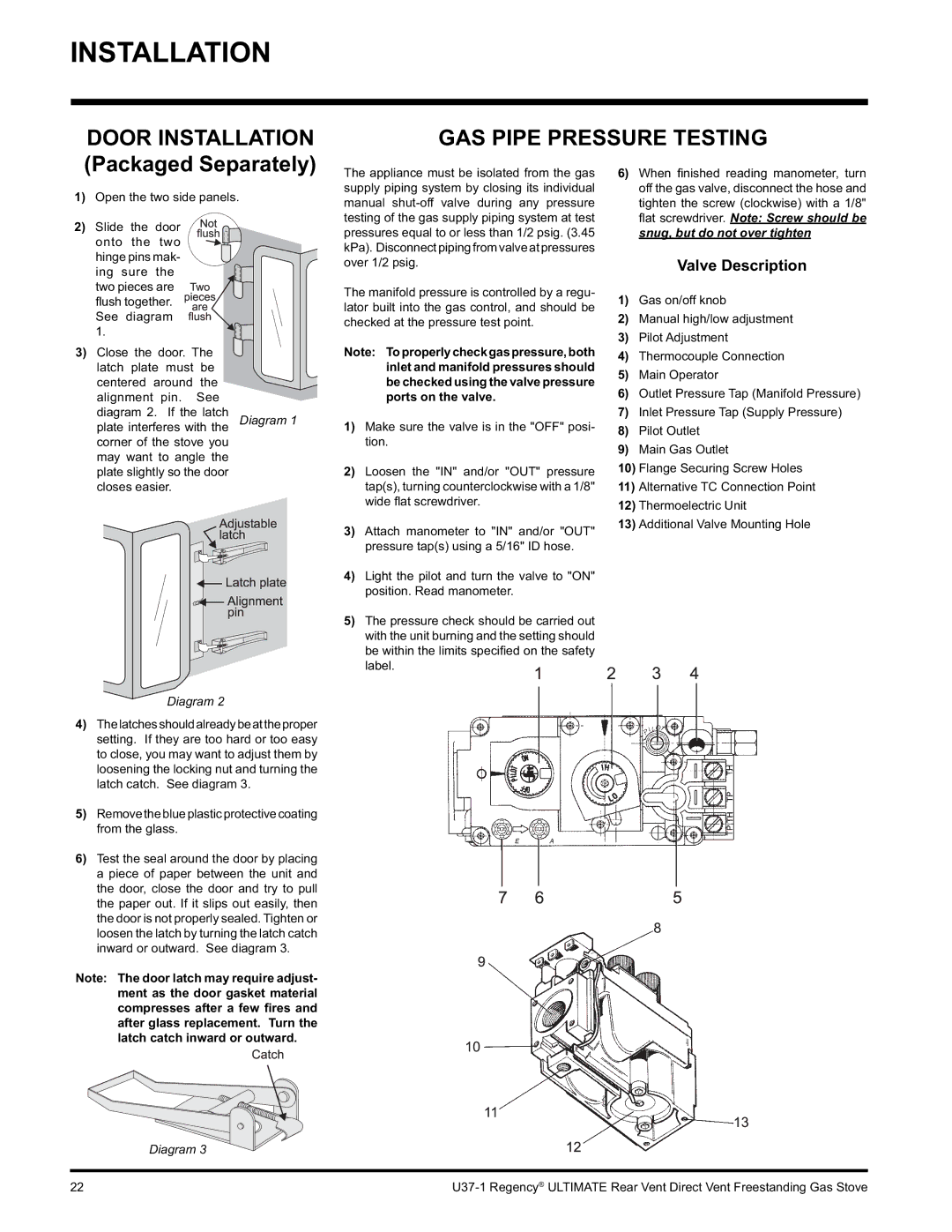
Valve Description

1)Gas on/off knob

2)Manual high/low adjustment

3)Pilot Adjustment

3) Close the door. The latch plate must be centered around the alignment pin. See

Note: Toproperlycheckgaspressure,both

4)

Thermocouple Connection

inlet and manifold pressures should

5)

Main Operator

be checked using the valve pressure

6)

Outlet Pressure Tap (Manifold Pressure)

ports on the valve.

diagram 2. If the latch

plate interferes with the Diagram 1 corner of the stove you

may want to angle the plate slightly so the door closes easier.

Diagram 2

4)Thelatchesshouldalreadybeattheproper setting. If they are too hard or too easy to close, you may want to adjust them by loosening the locking nut and turning the latch catch. See diagram 3.

5)Remove the blue plasticprotectivecoating from the glass.

6)Test the seal around the door by placing a piece of paper between the unit and the door, close the door and try to pull the paper out. If it slips out easily, then the door is not properly sealed. Tighten or loosen the latch by turning the latch catch inward or outward. See diagram 3.

Note: The door latch may require adjust- ment as the door gasket material compresses after a few fires and after glass replacement. Turn the latch catch inward or outward.

Diagram 3

1)Make sure the valve is in the "OFF" posi- tion.

2)Loosen the "IN" and/or "OUT" pressure tap(s), turning counterclockwise with a 1/8" wide fl at screwdriver.

3)Attach manometer to "IN" and/or "OUT" pressure tap(s) using a 5/16" ID hose.

4)Light the pilot and turn the valve to "ON" position. Read manometer.

5)The pressure check should be carried out

with the unit burning and the setting should be within the limits specifi ed on the safety label.

7)Inlet Pressure Tap (Supply Pressure)

8)Pilot Outlet

9)Main Gas Outlet

10)Flange Securing Screw Holes

11)Alternative TC Connection Point

12)Thermoelectric Unit

13)Additional Valve Mounting Hole

22

U37-1 Regency® ULTIMATE Rear Vent Direct Vent Freestanding Gas Stove

Page 22
Image 22
Regency U37-LP1, U37-NG1 GAS Pipe Pressure Testing, Valve Description, Thermocouple Connection, Ports on the valve

U37-LP1, U37-NG1 specifications

The Regency U37-NG1 and U37-LP1 are two innovative models that showcase advanced technology and superior engineering in the realm of HVAC (heating, ventilation, and air conditioning) systems. These units are designed to deliver optimal comfort while maximizing energy efficiency, making them ideal for both residential and commercial applications.

One of the standout features of the U37-NG1 is its use of a high-efficiency burner system, which ensures that every unit is capable of delivering substantial heating output while consuming minimal gas. This not only translates to lower utility bills for users but also aligns with sustainability goals by reducing carbon emissions. In terms of design, the U37-NG1 is compact and can be installed in a variety of settings, making it a versatile choice for many different environments.

The U37-LP1, on the other hand, is tailored for propane applications, making it perfect for areas where natural gas is inaccessible. It features a similar high-efficiency heating output, ensuring that it meets the demands of users without compromising on performance. The dual-fuel capability of the U37 series enhances its adaptability, allowing it to be used in a range of scenarios.

Both models are equipped with advanced control technologies, including programmable thermostats and smart connectivity features. Users can easily manage their heating systems through mobile apps, allowing for remote adjustments and real-time monitoring. This technology not only enhances user convenience but also promotes energy conservation by allowing users to adjust settings based on their lifestyle and preferences.

In terms of durability, the Regency U37 series boasts a robust construction designed to withstand various environmental conditions. With quality materials and expert craftsmanship, these units are built to last, reducing the need for frequent repairs or replacements.

Overall, the Regency U37-NG1 and U37-LP1 models combine cutting-edge technology with practical features to deliver an exceptional heating experience. Their commitment to energy efficiency, adaptability, and user-friendly controls positions them as leading options in the HVAC market, making comfortable living spaces more accessible while promoting environmentally responsible practices. Whether for home use or commercial properties, these systems offer reliability and performance tailored to the needs of modern users.