
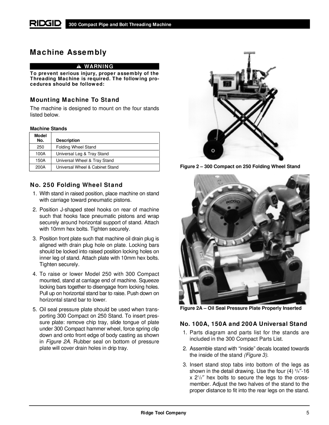
300 specifications
The RIDGID 300 is a highly regarded threading machine amongst plumbers and contractors, known for its durability, performance, and innovation in pipe threading. Designed for high-volume operations, this versatile tool can handle a wide range of pipe sizes, making it an indispensable asset in various plumbing projects.One of the main features of the RIDGID 300 is its robust construction. Built to withstand rigorous use in demanding environments, the machine boasts a heavy-duty frame and components that contribute to its longevity. The compact design allows for portability, making it easy to transport to job sites, while its solid base provides stability during operation.
The RIDGID 300 employs advanced technologies that enhance its efficiency and performance. The machine is equipped with a powerful electric motor that delivers consistent and reliable performance, enabling users to complete threading tasks quickly and effectively. A unique gear drive system allows for smooth operation, reducing wear and tear on the equipment while ensuring precision in threading.
Another notable characteristic of the RIDGID 300 is its ability to accommodate various pipe materials. The machine is designed to handle iron, steel, and other common materials, making it a flexible choice for different applications. Additionally, it features a quick-change die head, enabling operators to switch pipe sizes rapidly, significantly increasing productivity on the job site.
The RIDGID 300 includes thoughtful safety features that help protect users during operation. Its integrated safety features reduce the risk of injury, allowing operators to focus on their work with confidence. Furthermore, the machine’s maintenance-friendly design allows for easy access to components, ensuring that routine servicing and repairs can be conducted with minimal downtime.
The versatility and adaptability of the RIDGID 300 make it suited for a variety of threading applications. Whether used in residential, commercial, or industrial environments, this threading machine consistently delivers outstanding results, earning it a reputation as a go-to tool for professionals in the plumbing industry. Its combination of power, durability, and thoughtful design elements ensure that the RIDGID 300 remains an essential piece of equipment for threading tasks, keeping pipelines secure and leak-free.