ELECTRICAL
CHANGING MOTOR VOLTAGE
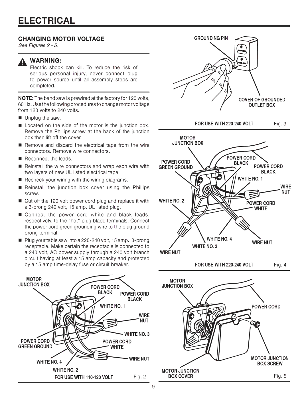
See Figures 2 - 5.
WARNING:
Electric shock can kill. To reduce the risk of serious personal injury, never connect plug to power source until all assembly steps are completed.
NOTE: The band saw is prewired at the factory for 120 volts, 60 Hz. Use the following procedures to change motor voltage from 120 volts to 240 volts.
nUnplug the saw.
nLocated on the side of the motor is the junction box. Remove the Phillips screw at the back of the junction box then lift off the cover.
nRemove and discard the electrical tape from the wire connectors. Remove wire connectors.
nReconnect the leads.
nReinstall the wire connectors and wrap each wire with two layers of new UL listed electrical tape.
nRecheck your wiring with the wiring diagrams.
nReinstall the junction box cover using the Phillips screw.
nCut off the 120 volt power cord plug and replace it with a
nConnect the power cord white and black leads, respectively, to the "hot" plug blade terminals. Connect the power cord green grounding wire to the plug ground prong terminal.
nPlug your table saw into a
MOTOR |
|
|
JUNCTION BOX | POWER CORD |
|
|
| |
| BLACK | POWER CORD |
|
| BLACK |
| WHITE NO. 1 | |
|
| WIRE |
|
| NUT |
|
| WHITE NO. 3 |
POWER CORD | POWER CORD | |
GREEN GROUND | WHITE | |
WHITE NO. 4 | WIRE NUT | |
| ||
| WHITE NO. 2 |
|
| FOR USE WITH | Fig. 2 |
GROUNDING PIN
| COVER OF GROUNDED | |
| OUTLET BOX | |
FOR USE WITH | Fig. 3 | |
MOTOR |
|
|
JUNCTION BOX |
|
|
POWER CORD | POWER CORD | |
BLACK | POWER CORD | |
GREEN GROUND |
| |
|
| BLACK |
| WHITE NO. 1 | |
|
| WIRE |
|
| NUT |
WHITE NO. 2 | POWER CORD | |
| ||
|
| WHITE |
WHITE NO. 4 | WIRE NUT | |
WHITE NO. 3 | ||
| ||
WIRE NUT |
|
FOR USE WITH | Fig. 4 |
|
|
MOTOR |
|
JUNCTION BOX |
|
POWER CORD
| MOTOR JUNCTION |
| BOX SCREW |
MOTOR JUNCTION | Fig. 5 |
BOX COVER |
9
