ASSEMBLY
UNPACKING
This product requires assembly.
nCarefully remove the tool and any accessories from the box. Place it on a level work surface.
NOTE: This tool is heavy. To avoid back injury, lift with your legs, not your back, and get help when needed.
nInspect the tool carefully to make sure no breakage or damage occurred during shipping.
nDo not discard the packing material until you have carefully inspected the tool, identified all loose parts, and satisfactorily operated the tool.
nRemove the protective oil that is applied to all unpainted metal surfaces. Use any ordinary household type grease and spot remover.
nApply coat of paste wax to the saw table.
nThe saw is factory set for accurate cutting. After assem- bling it, check for accuracy. If shipping has influenced the settings, refer to specific procedures explained in the operation and maintenance sections of this manual.
nIf any parts are damaged or missing, please call
WARNING:
If any parts are missing, do not operate this tool until the missing parts are replaced. Failure to do so could result in possible serious personal injury.
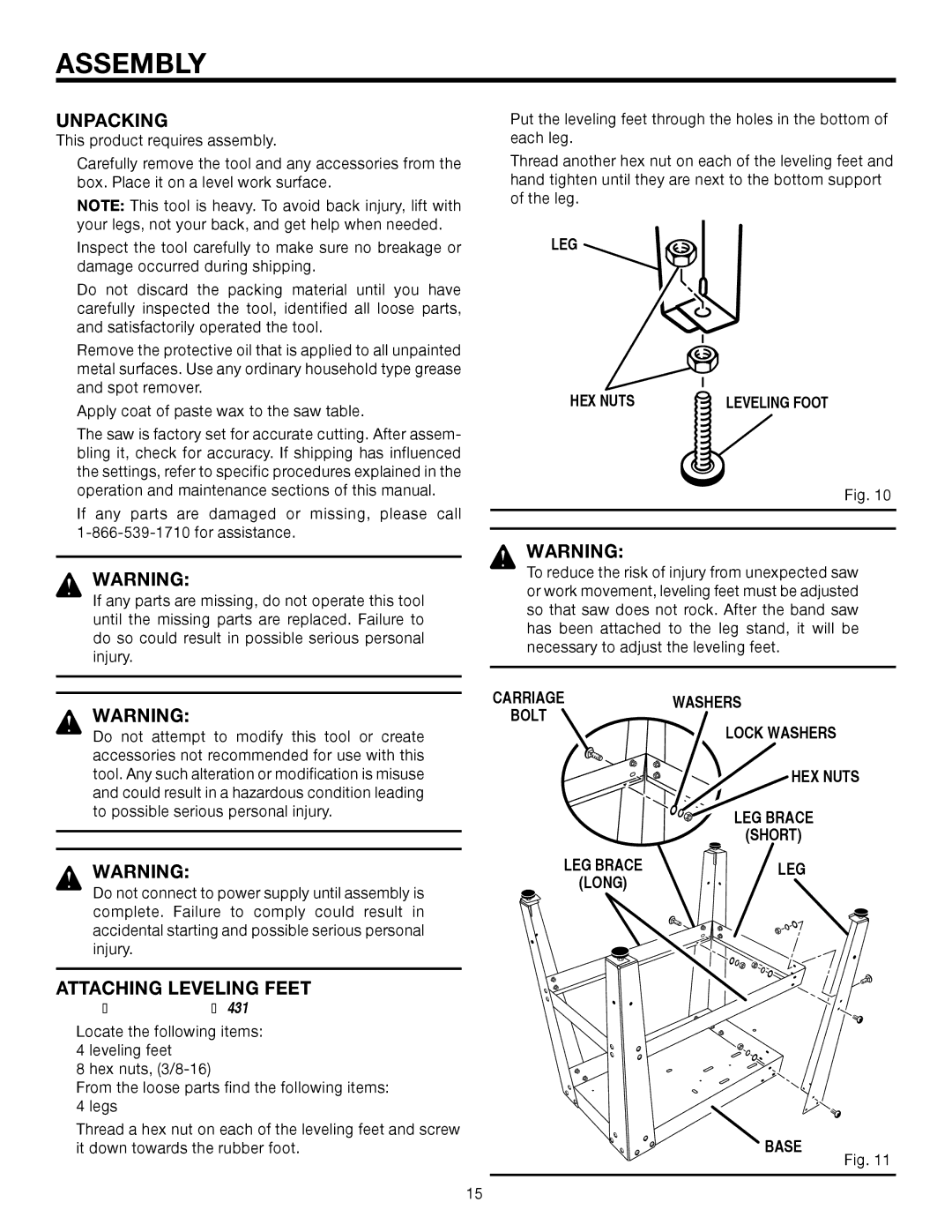
nPut the leveling feet through the holes in the bottom of each leg.
nThread another hex nut on each of the leveling feet and hand tighten until they are next to the bottom support of the leg.
LEG
HEX NUTS | LEVELING FOOT |
Fig. 10
WARNING:
To reduce the risk of injury from unexpected saw or work movement, leveling feet must be adjusted so that saw does not rock. After the band saw has been attached to the leg stand, it will be necessary to adjust the leveling feet.
WARNING:
Do not attempt to modify this tool or create accessories not recommended for use with this tool. Any such alteration or modification is misuse and could result in a hazardous condition leading to possible serious personal injury.
WARNING:
Do not connect to power supply until assembly is complete. Failure to comply could result in accidental starting and possible serious personal injury.
ATTACHING LEVELING FEET
See Figure 10.
nLocate the following items:
4 leveling feet
8 hex nuts,
nFrom the loose parts find the following items:
4 legs
nThread a hex nut on each of the leveling feet and screw it down towards the rubber foot.
CARRIAGE | WASHERS |
BOLT | LOCK WASHERS |
| |
| HEX NUTS |
| LEG BRACE |
| (SHORT) |
LEG BRACE | LEG |
(LONG) |
|
BASE
Fig. 11
15