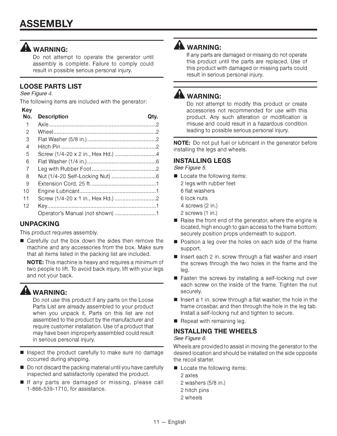
ASSEMBLY

WARNING:

Do not attempt to operate the generator until assembly is complete. Failure to comply could result in possible serious personal injury.

LOOSE PARTS LIST

See Figure 4.

The following items are included with the generator:

Key


No.

Description

Qty.

1

Axle

2

2

Wheel

2

3

Flat Washer (5/8 in.)

2

4

Hitch Pin

2

5

Screw (1/4-20 x 2 in., Hex Hd.)

4

6

Flat Washer (1/4 in.)

6

7

Leg with Rubber Foot

2

8

Nut (1/4-20 Self-Locking Nut)

6

9

Extension Cord, 25 ft

1

10

Engine Lubricant

1

11

Screw (1/4-20 x 1 in., Hex Hd.)

2

12

Key

1


Operator’s Manual (not shown)

1

UNPACKING

This product requires assembly.

Carefully cut the box down the sides then remove the machine and any accessories from the box. Make sure that all items listed in the packing list are included.

NOTE: This machine is heavy and requires a minimum of two people to lift. To avoid back injury, lift with your legs and not your back.

WARNING:

Do not use this product if any parts on the Loose Parts List are already assembled to your product when you unpack it. Parts on this list are not assembled to the product by the manufacturer and require customer installation. Use of a product that may have been improperly assembled could result in serious personal injury.

Inspect the product carefully to make sure no damage occurred during shipping.

Do not discard the packing material until you have carefully­ inspected and satisfactorily operated the product­.

If any parts are damaged or missing, please call 1-866-539-1710, for assistance.

WARNING:

If any parts are damaged or missing do not operate this product until the parts are replaced. Use of this product with damaged or missing parts could result in serious personal injury.

WARNING:

Do not attempt to modify this product or create accessories not recommended for use with this product. Any such alteration or modification is misuse and could result in a hazardous condition leading to possible serious personal injury.

NOTE:  Do not put fuel or lubricant in the generator before installing the legs and wheels.

installing LEGS

See Figure 5.

Locate the following items:

2 legs with rubber feet

6 flat washers

6 lock nuts

4 screws (2 in.)

2 screws (1 in.)

Raise the front end of the generator, where the engine is located, high enough to gain access to the frame bottom; securely position props underneath to support.

Position a leg over the holes on each side of the frame support.

Insert each 2 in. screw through a flat washer and insert the screws through the two holes in the frame and the leg.

Fasten the screws by installing a self-locking nut over each screw on the inside of the frame. Tighten the nut securely.

Insert a 1 in. screw through a flat washer, the hole in the frame crossbar, and then through the hole in the leg tab. Install a self-locking nut and tighten to secure.

Repeat with remaining leg.

installing the wheels

See Figure 6.

Wheels are provided to assist in moving the generator to the desired location and should be installed on the side opposite the recoil starter.

Locate the following items: 2 axles

2 washers (5/8 in.)

2 hitch pins

2 wheels

11 — English

Page 11
Image 11
RIDGID RD8000, RD80011 manuel dutilisation Assembly, Loose Parts List, Unpacking, Installing Legs, Installing the wheels

RD80011, RD8000 specifications

The RIDGID RD8000 and RD80011 represent a significant advancement in the world of underground utility locating. These versatile tools are designed to help professionals accurately detect and trace buried utilities, ensuring safe and efficient excavation and construction processes.

Both models are equipped with advanced signal processing technologies that enhance their ability to locate utilities, even in challenging environments. The RD8000 is renowned for its range of frequencies—typically offering up to five different transmission frequencies, allowing users to locate a variety of utility types including electric, gas, water, and telecommunications lines. This frequency versatility means that users can effectively cater to a wide spectrum of application needs, from residential projects to large-scale infrastructure work.

The RD80011 variant enhances these capabilities with added features aimed at improving user experience and precision. One standout feature is the built-in GPS technology, which allows for real-time mapping and locating of utilities, providing users with the ability to track locations directly on their devices. This integration streamlines the process of recording and reporting utility locations, fostering efficient workflow and reducing the risk of errors in documentation.

Additionally, both models boast an ergonomic design, featuring a lightweight build and intuitive controls that make them user-friendly. The display screen is bright and easy to read, featuring visual indicators that help convey critical information at a glance. The RD8000 and RD80011 utilize a rechargeable battery that ensures long-lasting power, giving users the confidence to tackle extended projects without the need to frequently replace batteries.

Another valuable characteristic is the built-in earphone jack, allowing for enhanced audio feedback and communication in noisy environments. Users can listen for specific tones corresponding to different utilities, which can aid in pinpointing the location with greater accuracy.

These RIDGID models also include advanced interference suppression technologies to minimize signal distortion from other nearby utilities, ensuring users receive clear and accurate data. This feature is particularly vital in complex urban settings where multiple utilities coexist in close proximity.

In summary, both the RIDGID RD8000 and RD80011 are designed with professional utility locators in mind, integrating advanced technologies and features that enhance detection capabilities, improve ease of use, and contribute to safer excavation practices.