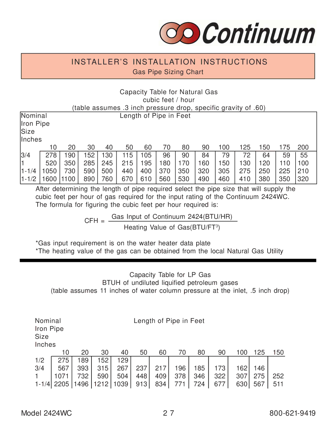
INSTALLER’S INSTALLATION INSTRUCTIONS
Gas Pipe Sizing Chart
Capacity Table for Natural Gas
cubic feet / hour
(table assumes .3 inch pressure drop, specific gravity of .60)
Nominal |
|
|
| Length of Pipe in Feet |
|
|
|
|
|
| |||||
Iron Pipe |
|
|
|
|
|
|
|
|
|
|
|
|
| ||
Size |
|
|
|
|
|
|
|
|
|
|
|
|
|
| |
Inches | 10 | 20 | 30 | 40 | 50 | 60 | 70 | 80 | 90 | 100 | 125 | 150 | 175 | 200 | |
3/4 |
| ||||||||||||||
| 278 | 190 | 152 | 130 | 115 | 105 | 96 | 90 | 84 | 79 | 72 | 64 | 59 | 55 | |
1 |
| 520 | 350 | 285 | 245 | 215 | 195 | 180 | 170 | 160 | 150 | 130 | 120 | 110 | 100 |
| 1050 | 730 | 590 | 500 | 440 | 400 | 370 | 350 | 320 | 305 | 275 | 250 | 225 | 210 | |
| 1600 | 1100 | 890 | 760 | 670 | 610 | 560 | 530 | 490 | 460 | 410 | 380 | 350 | 320 | |
After determining the length of pipe required select the pipe size that will supply the cubic feet per hour of gas required for the input rating of the Continuum 2424WC. The formula for figuring the cubic feet per hour required is:
CFH = Gas Input of Continuum 2424(BTU/HR)
Heating Value of Gas(BTU/FT3)
*Gas input requirement is on the water heater data plate
*The heating value of the gas can be obtained from the local Natural Gas Utility
Capacity Table for LP Gas
BTUH of undiluted liquified petroleum gases
(table assumes 11 inches of water column pressure at the inlet, .5 inch drop)
Nominal | Length of Pipe in Feet |
Iron Pipe |
|
Size |
|
Inches |
|
1/2
3/4
1
10 | 20 | 30 | 40 | 50 | 60 | 70 | 80 | 90 | 100 | 125 | 150 |
275 | 189 | 152 | 129 |
|
|
|
|
|
|
|
|
567 | 393 | 315 | 267 | 237 | 217 | 196 | 185 | 173 | 162 | 146 |
|
1071 | 732 | 590 | 504 | 448 | 409 | 378 | 346 | 322 | 307 | 275 | 252 |
2205 | 1496 | 1212 | 1039 | 913 | 834 | 771 | 724 | 677 | 630 | 567 | 511 |
Model 2424WC | 2 7 |