|
|
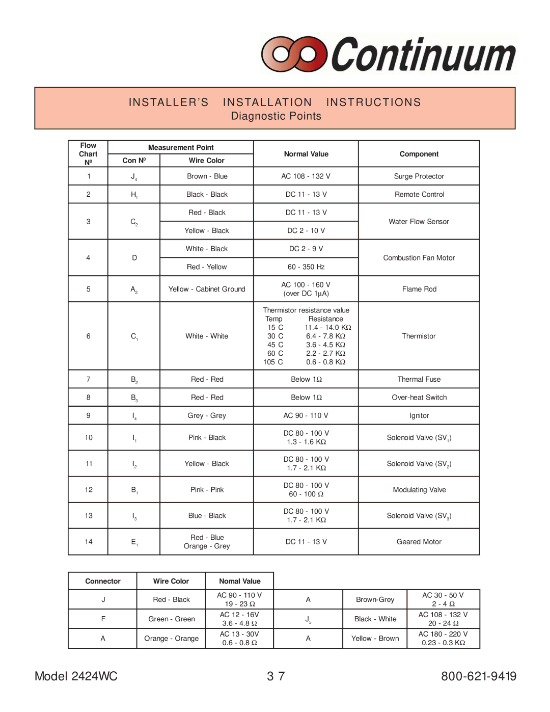
| INSTALLER’S | INSTALLATION INSTRUCTIONS | ||||||||||||||||
|
|
|
|
|
|
|
| Diagnostic Points |
|
|
|
|
|
|
| |||||
|
|
|
|
|
|
|
|
|
|
|
|
|
|
|
|
|
|
|
|
|
|
|
|
|
|
|
|
|
|
|
|
|
|
|
|
|
|
|
|
|
|
| Flow |
|
|
| Measurement Point |
|
|
|
|
|
|
|
|
|
|
|
|
| ||
| Chart |
|
|
|
|
|
|
| Normal Value |
|
|
|
| Component |
| |||||
|
|
|
|
|
|
|
|
|
|
|
|
|
|
|
| |||||
|
| Con N0 |
| Wire Color |
|
|
|
|
|
|
| |||||||||
| 0 |
|
|
|
|
|
|
|
|
|
|
|
|
|
| |||||
| N |
|
|
|
|
|
|
|
|
|
|
|
|
|
|
|
|
|
|
|
| 1 |
| J4 |
| Brown - Blue |
|
| AC 108 - 132 V |
| Surge Protector |
| |||||||||
|
|
|
|
|
|
|
|
|
|
|
|
|
|
|
|
|
| |||
| 2 |
| H1 |
| Black - Black |
|
|
| DC 11 - 13 V |
|
| Remote Control |
| |||||||
|
|
|
|
|
|
|
|
|
|
|
|
|
|
|
|
|
|
|
| |
|
|
|
|
|
| Red - Black |
|
|
| DC 11 - 13 V |
|
|
|
|
|
|
| |||
| 3 |
| C2 |
|
|
|
|
|
|
|
|
|
| Water Flow Sensor |
| |||||
|
| Yellow - Black |
|
|
| DC 2 - 10 V |
| |||||||||||||
|
|
|
|
|
|
|
|
|
|
|
|
|
|
|
| |||||
|
|
|
|
|
|
|
|
|
|
|
|
|
|
|
|
|
|
|
| |
|
|
|
|
|
| White - Black |
|
|
| DC 2 - 9 V |
|
|
|
|
|
|
| |||
| 4 |
| D |
|
|
|
|
|
|
|
|
|
| Combustion Fan Motor |
| |||||
|
| Red - Yellow |
|
|
| 60 - 350 Hz |
| |||||||||||||
|
|
|
|
|
|
|
|
|
|
|
|
|
|
|
| |||||
|
|
|
|
|
|
|
|
|
|
|
|
|
|
|
|
|
|
|
| |
| 5 |
| A2 |
| Yellow - Cabinet Ground |
|
| AC 100 - 160 V |
|
|
|
| Flame Rod |
| ||||||
|
|
|
|
|
| (over DC 1µA) |
|
|
|
|
| |||||||||
|
|
|
|
|
|
|
|
|
|
|
|
|
|
|
|
|
|
| ||
|
|
|
|
|
|
|
|
|
|
|
|
|
|
|
|
|
|
|
| |
|
|
|
|
|
|
|
|
|
| Thermistor resistance value |
|
|
|
|
|
|
| |||
|
|
|
|
|
|
|
|
|
| Temp | Resistance |
|
|
|
|
|
|
| ||
|
|
|
|
|
|
|
|
|
| 15°C | 11.4 - 14.0 KΩ |
|
|
|
|
|
|
| ||
| 6 |
| C1 |
| White - White |
| 30°C | 6.4 - 7.8 KΩ |
|
|
|
| Thermistor |
| ||||||
|
|
|
|
|
|
|
|
|
| 45°C | 3.6 - 4.5 KΩ |
|
|
|
|
|
|
| ||
|
|
|
|
|
|
|
|
|
| 60°C | 2.2 - 2.7 KΩ |
|
|
|
|
|
|
| ||
|
|
|
|
|
|
|
|
|
| 105°C | 0.6 - 0.8 KΩ |
|
|
|
|
|
|
| ||
|
|
|
|
|
|
|
|
|
|
|
|
|
|
|
|
|
|
| ||
| 7 |
| B2 |
| Red - Red |
|
|
| Below 1Ω |
|
|
| Thermal Fuse |
| ||||||
|
|
|
|
|
|
|
|
|
|
|
|
|
|
|
|
| ||||
| 8 |
| B3 |
| Red - Red |
|
|
| Below 1Ω |
|
| |||||||||
|
|
|
|
|
|
|
|
|
|
|
|
|
|
|
|
|
|
|
| |
| 9 |
| I4 |
| Grey - Grey |
|
|
| AC 90 - 110 V |
|
|
|
|
| Ignitor |
| ||||
|
|
|
|
|
|
|
|
|
|
|
|
|
|
|
|
|
|
|
|
|
| 10 |
| I1 |
| Pink - Black |
|
|
| DC 80 - 100 V |
| Solenoid Valve (SV1) |
| ||||||||
|
|
|
|
|
| 1.3 - 1.6 KΩ |
|
| ||||||||||||
|
|
|
|
|
|
|
|
|
|
|
|
|
|
|
|
|
|
| ||
|
|
|
|
|
|
|
|
|
|
|
|
|
|
|
|
|
|
|
|
|
| 11 |
| I2 |
| Yellow - Black |
|
|
| DC 80 - 100 V |
| Solenoid Valve (SV2) |
| ||||||||
|
|
|
|
|
| 1.7 - 2.1 KΩ |
|
| ||||||||||||
|
|
|
|
|
|
|
|
|
|
|
|
|
|
|
|
|
|
| ||
|
|
|
|
|
|
|
|
|
|
|
|
|
|
|
|
|
|
|
|
|
| 12 |
| B1 |
| Pink - Pink |
|
|
| DC 80 - 100 V |
| Modulating Valve |
| ||||||||
|
|
|
|
|
| 60 - 100 Ω |
|
| ||||||||||||
|
|
|
|
|
|
|
|
|
|
|
|
|
|
|
|
|
|
| ||
|
|
|
|
|
|
|
|
|
|
|
|
|
|
|
|
|
|
|
|
|
| 13 |
| I3 |
| Blue - Black |
|
|
| DC 80 - 100 V |
| Solenoid Valve (SV3) |
| ||||||||
|
|
|
|
|
| 1.7 - 2.1 KΩ |
|
| ||||||||||||
|
|
|
|
|
|
|
|
|
|
|
|
|
|
|
|
|
|
| ||
|
|
|
|
|
|
|
|
|
|
|
|
|
|
|
|
|
|
|
| |
| 14 |
| E1 |
| Red - Blue |
|
|
| DC 11 - 13 V |
|
|
| Geared Motor |
| ||||||
|
|
| Orange - Grey |
|
|
|
|
|
|
| ||||||||||
|
|
|
|
|
|
|
|
|
|
|
|
|
|
|
|
|
| |||
|
|
|
|
|
|
|
|
|
|
|
|
|
|
|
|
|
|
|
| |
|
|
|
|
|
|
|
|
|
|
|
|
|
|
|
|
| ||||
| Connector |
|
| Wire Color |
| Nomal Value |
|
|
|
|
|
|
|
|
|
| ||||
|
|
|
|
|
|
|
|
|
|
|
|
|
|
|
|
|
|
| ||
| J |
|
| Red - Black |
| AC 90 - 110 V |
| A |
|
|
|
| AC 30 - 50 V |
| ||||||
|
|
|
| 19 - 23 | Ω |
|
|
|
|
| 2 - 4 Ω |
| ||||||||
|
|
|
|
|
|
|
|
|
|
|
|
|
|
|
|
| ||||
| F |
|
| Green - Green |
| AC 12 - 16V |
| J5 |
| Black - White |
|
| AC 108 - 132 V |
| ||||||
|
|
|
| 3.6 - 4.8 | Ω |
|
|
|
| 20 - 24 Ω |
| |||||||||
|
|
|
|
|
|
|
|
|
|
|
|
|
|
|
|
| ||||
| A |
| Orange - Orange |
| AC 13 - 30V |
| A |
| Yellow - Brown |
| AC 180 - 220 V |
| ||||||||
|
|
| 0.6 - 0.8 | Ω |
|
|
| 0.23 - 0.3 KΩ |
| |||||||||||
|
|
|
|
|
|
|
|
|
|
|
|
|
|
|
|
| ||||
Model 2424WC | 3 7 |