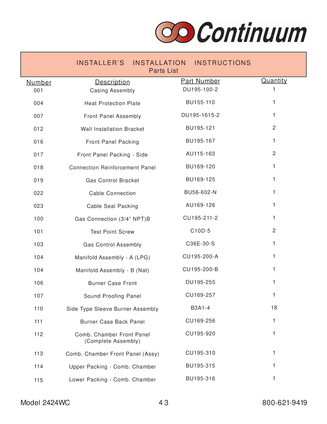
INSTALLER’S INSTALLATION INSTRUCTIONS
Parts List
Number | Description |
001 | Casing Assembly |
004 | Heat Protection Plate |
007 | Front Panel Assembly |
012 | Wall Installation Bracket |
016 | Front Panel Packing |
017Front Panel Packing - Side
018Connection Reinforcement Panel
019 | Gas Control Bracket |
022 | Cable Connection |
023 | Cable Seal Packing |
100 | Gas Connection (3/4” NPT)B |
101 | Test Point Screw |
103 | Gas Control Assembly |
104 | Manifold Assembly - A (LPG) |
104 | Manifold Assembly - B (Nat) |
106 | Burner Case Front |
107 | Sound Proofing Panel |
110 | Side Type Sleeve Burner Assembly |
111 | Burner Case Back Panel |
112Comb. Chamber Front Panel
(Complete Assembly)
113Comb, Chamber Front Panel (Assy)
114Upper Packing - Comb. Chamber
115Lower Packing - Comb. Chamber
Part Number
Quantity
1
1
1
2
1
2
1
1
1
1
1
2
1
1
1
1
1
18
1
1
1
1
1
Model 2424WC | 4 3 |
