ROBERTS GOR DON®
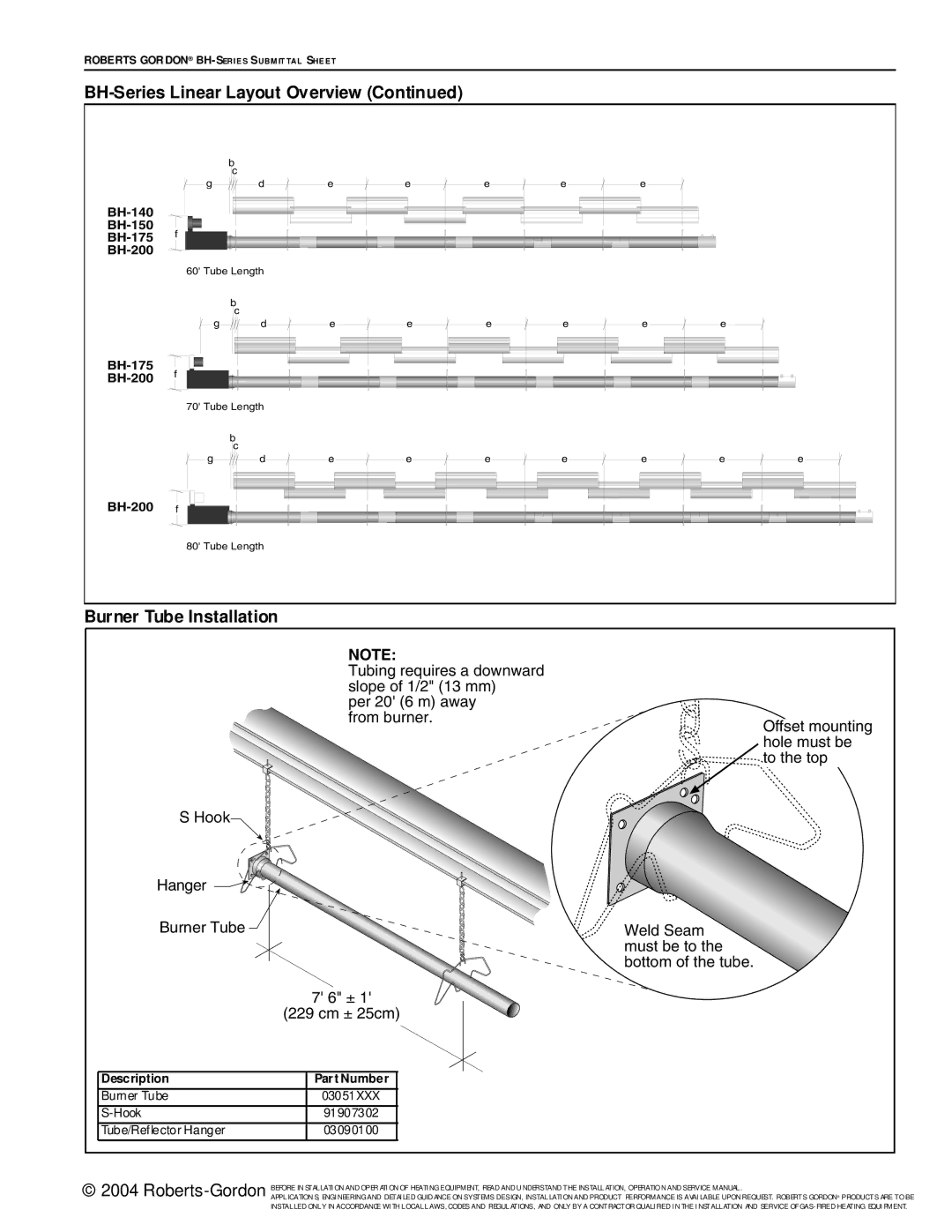
BH-Series Linear Layout Overview (Continued)
|
| bc |
|
|
|
|
|
|
|
| g | d | e | e | e | e | e |
|
|
|
|
|
|
|
|
|
|
| |
f |
|
|
|
|
|
|
|
| |
|
|
|
|
|
|
|
| ||
|
|
|
|
|
|
|
|
| |
| 60' Tube Length |
|
|
|
|
|
|
| |
|
| bc |
|
|
|
|
|
|
|
| g | d | e | e | e | e | e | e |
|
f |
|
|
|
|
|
|
|
| |
|
|
|
|
|
|
|
| ||
| 70' Tube Length |
|
|
|
|
|
|
| |
|
| bc |
|
|
|
|
|
|
|
| g | d | e | e | e | e | e | e | e |
f |
|
|
|
|
|
|
|
| |
| 80' Tube Length |
|
|
|
|
|
|
| |
Burner Tube Installation
NOTE:
Tubing requires a downward slope of 1/2" (13 mm)
per 20' (6 m) away from burner.
Offset mounting hole must be to the top
S Hook
Hanger |
Burner Tube
| 7' 6" ± 1' |
| |
| (229 cm ± 25cm) | ||
|
|
|
|
Description |
| Part Number |
|
Burner Tube |
| 03051XXX |
|
|
| 91907302 |
|
Tube/Reflector Hanger |
| 03090100 |
|
Weld
must be to the bottom of the tube
© 2004
APPLICATION S, ENGI NEERING AND DETAI LED GUID ANCE ON SYSTEMS DESIGN, INSTALLATI ON AND PRODUCT PERFORMANCE IS AVAI LABLE UPON REQUEST. ROBERTS GORDON® PRODUCTS ARE TO BE INSTALLED ONLY IN ACCORDANCE WI TH LOCAL LAWS, CODES AND REGULATIONS, AND ONLY BY A CONTRACTOR QUALI FIED I N THE I NSTALLATION AND SERVICE OF