ROBERTS GORDON ®
NOTE: 1. All dimensions are from the surfaces of all tubes, couplings and elbows.
2.Clearances B, C and D can be reduced by 50% after 25' (7.5 m) of tubing downstream from where the burner and burner tube connect.
3.
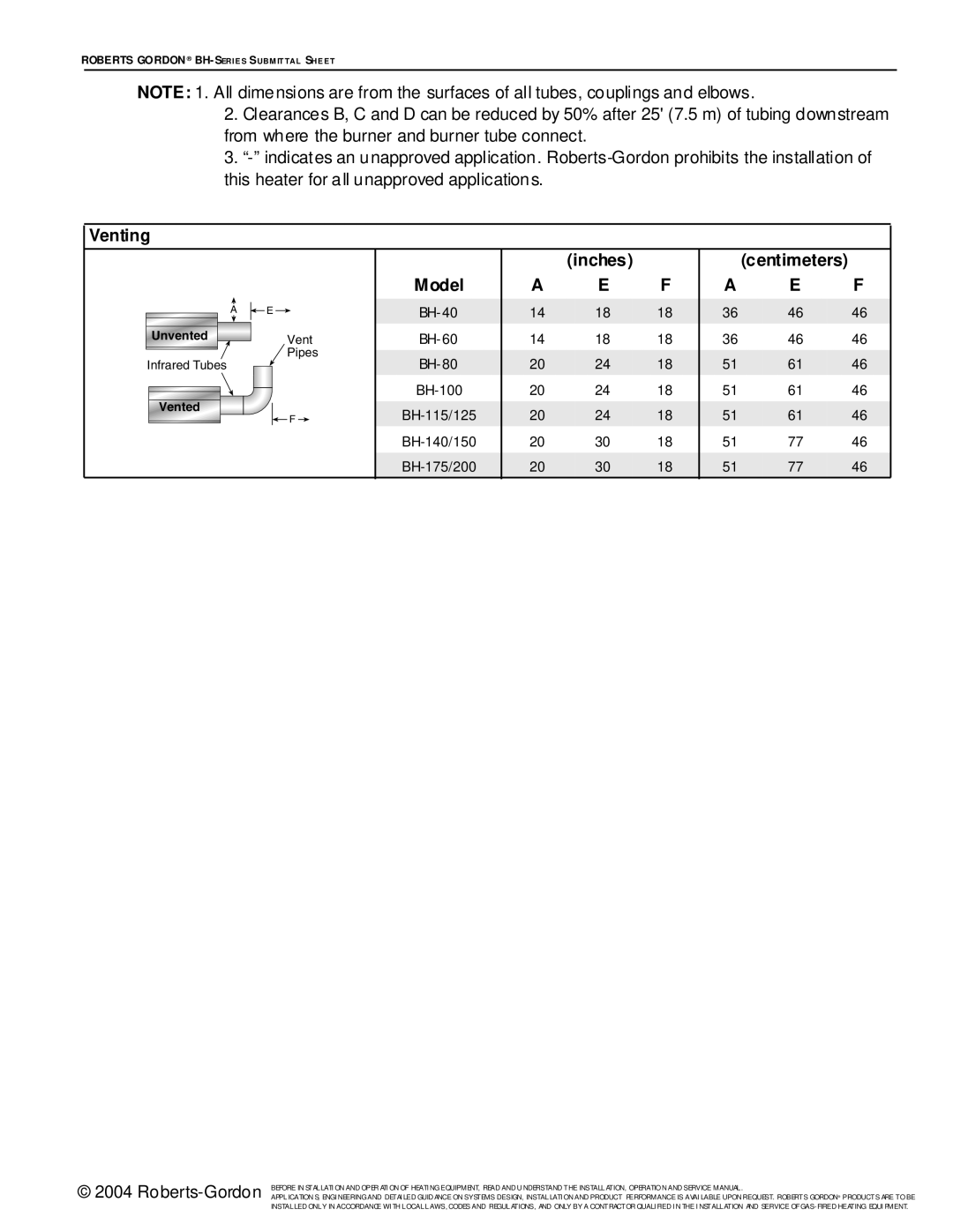
Venting
|
|
|
| (inches) |
|
| (centimeters) |
| |
|
| Model | A | E | F | A | E | F | |
A | E |
| 14 | 18 | 18 | 36 | 46 | 46 | |
Unvented | Vent |
| 14 | 18 | 18 | 36 | 46 | 46 | |
Infrared Tubes | Pipes |
| 20 | 24 | 18 | 51 | 61 | 46 | |
| |||||||||
Vented |
|
| 20 | 24 | 18 | 51 | 61 | 46 | |
F |
| 20 | 24 | 18 | 51 | 61 | 46 | ||
| |||||||||
|
|
| 20 | 30 | 18 | 51 | 77 | 46 | |
|
|
| 20 | 30 | 18 | 51 | 77 | 46 |
© 2004 | BEFORE IN STALLATI ON AND OPER ATI ON OF HEATI NG EQUIPMENT, READ AND U NDERSTAND THE INSTALLATION, OPERATIO N AND SERVICE MANUAL . |
APPLICATION S, ENGI NEERING AND DETAI LED GUID ANCE ON SYSTEMS DESIGN, INSTALLATI ON AND PRODUCT PERFORMANCE IS AVAI LABLE UPON REQUEST. ROBERTS GORDON® PRODUCTS ARE TO BE | |
| INSTALLED ONLY IN ACCORDANCE WI TH LOCAL LAWS, CODES AND REGULATIONS, AND ONLY BY A CONTRACTOR QUALI FIED I N THE I NSTALLATION AND SERVICE OF |