ROBERTS GOR DON®
Reflector, U-Clip and Reflector Support Installation
The pictorial drawings of the heater construction in this section are schematic only and provide a general guideline of where hangers, reflector supports and
To ensure proper expansion and contraction move- ment of the reflectors, a combination of
tor supports and
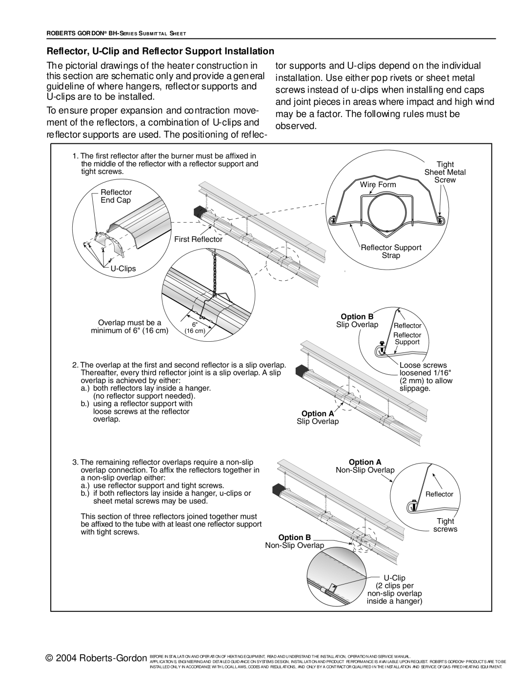
1.The first reflector after the burner must be affixed in the middle of the reflector with a reflector support and tight screws.
End
First Reflector
![]()
Overlap must be a | 6" |
minimum of 6" (16 cm) | (16 cm) |
2.The overlap at the first and second reflector is a slip overlap. Thereafter, every third reflector joint is a slip overlap. A slip overlap is achieved by either:
a.) both reflectors lay inside a hanger. (no reflector support needed).
b.) using a reflector support with loose screws at the reflector overlap.
| Tight |
| Sheet Metal |
Wire Form | Screw |
|
![]() Reflector Support
Reflector Support
Strap
Option B
Slip Overlap Reflector
Reflector
Support
![]() Loose screws
Loose screws
loosened 1/16"
(2 mm) to allow
slippage.
Option A
Slip Overlap
3.The remaining reflector overlaps require a
a.) use reflector support and tight screws.
b.) if both reflectors lay inside a hanger,
This section of three reflectors joined together must be affixed to the tube with at least one reflector support with tight screws.
Option A
Option B
![]() Reflector
Reflector
Tight
screws
(2 clips per
© 2004
APPLICATION S, ENGI NEERING AND DETAI LED GUID ANCE ON SYSTEMS DESIGN, INSTALLATI ON AND PRODUCT PERFORMANCE IS AVAI LABLE UPON REQUEST. ROBERTS GORDON® PRODUCTS ARE TO BE INSTALLED ONLY IN ACCORDANCE WI TH LOCAL LAWS, CODES AND REGULATIONS, AND ONLY BY A CONTRACTOR QUALI FIED I N THE I NSTALLATION AND SERVICE OF