ROBERTS GOR DON®
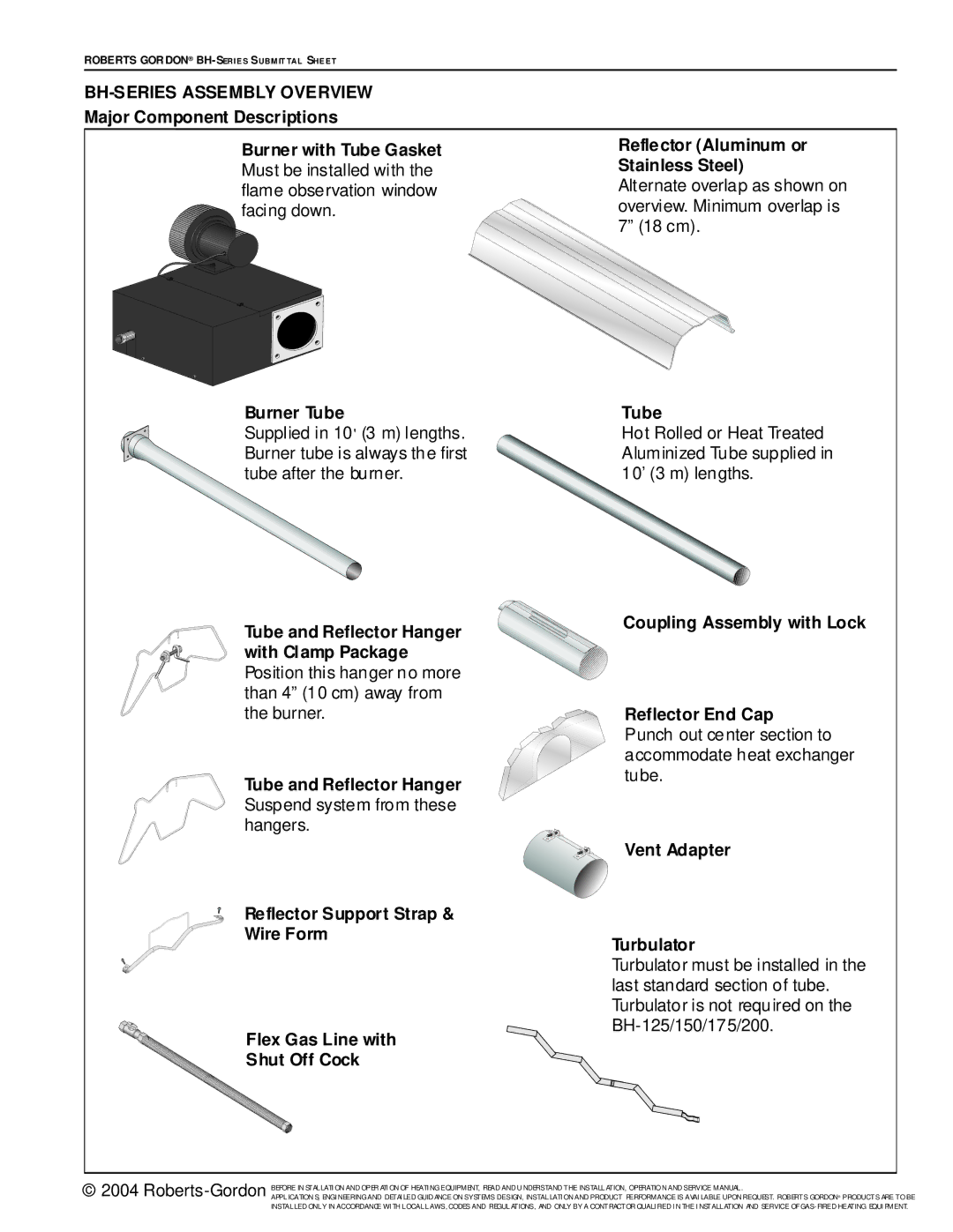
BH-SERIES ASSEMBLY OVERVIEW
Major Component Descriptions
Burner with Tube Gasket | Reflector (Aluminum or | |
Must be installed with the | Stainless Steel) | |
flame observation window | Alternate overlap as shown on | |
facing down. | overview. Minimum overlap is | |
|
| 7” (18 cm). |
|
|
|
|
|
|
Burner Tube | Tube |
Supplied in 10' (3 m) lengths. | Hot Rolled or Heat Treated |
Burner tube is always the first | Aluminized Tube supplied in |
tube after the burner. | 10’ (3 m) lengths. |
Tube and Reflector Hanger | Coupling Assembly with Lock |
| |
with Clamp Package |
|
Position this hanger no more |
|
than 4” (10 cm) away from |
|
the burner. | Reflector End Cap |
| Punch out center section to |
| accommodate heat exchanger |
Tube and Reflector Hanger | tube. |
| |
Suspend system from these |
|
hangers. |
|
| Vent Adapter |
Reflector Support Strap & Wire Form
Flex Gas Line with
Shut Off Cock
Turbulator
Turbulator must be installed in the last standard section of tube. Turbulator is not required on the
© 2004
APPLICATION S, ENGI NEERING AND DETAI LED GUID ANCE ON SYSTEMS DESIGN, INSTALLATI ON AND PRODUCT PERFORMANCE IS AVAI LABLE UPON REQUEST. ROBERTS GORDON® PRODUCTS ARE TO BE INSTALLED ONLY IN ACCORDANCE WI TH LOCAL LAWS, CODES AND REGULATIONS, AND ONLY BY A CONTRACTOR QUALI FIED I N THE I NSTALLATION AND SERVICE OF