ROBERTS GORDON ®
GENERAL SPECIFICATIONS
Material Specification
Reflectors
.024 Aluminum
Heater Specifications
Ignition
Fully automatic spark ignition with safety
Suspension Specifications
Hang heater with materials with a minimum working load of 75 lbs (33 kg).
Controls Specifications
Time switches, thermostats, etc. can be wired into the electrical supply. External controls supplied as an optional extra.
General Specifications for
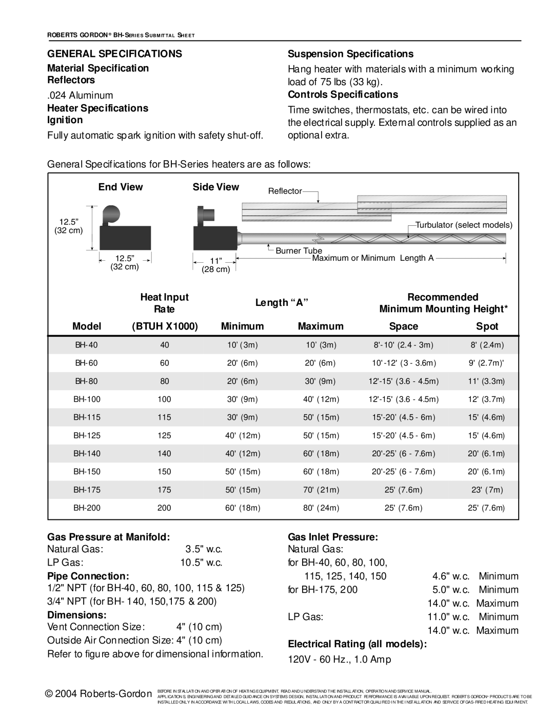
End View | Side View | Reflector |
|
| ||
|
|
|
|
|
| |
12.5” |
|
|
|
| Turbulator (select models) | |
(32 cm) |
|
|
|
| ||
|
|
|
|
|
| |
| 12.5” |
|
| Burner Tube |
|
|
|
| 11” | Maximum or Minimum Length A |
| ||
| (32 cm) |
|
|
|
| |
|
| (28 cm) |
|
|
| |
|
|
|
|
|
| |
| Heat Input |
| Length “A” | Recommended | ||
| Rate |
| Minimum Mounting Height* | |||
|
|
|
| |||
Model | (BTUH X1000) | Minimum | Maximum | Space | Spot | |
40 |
| 10’ (3m) | 10’ (3m) | 8' (2.4m) | ||
60 |
| 20' (6m) | 20' (6m) | 9' (2.7m)' | ||
80 |
| 20' (6m) | 30' (9m) | 11' (3.3m) | ||
100 |
| 30' (9m) | 40' (12m) | 12' (3.7m) | ||
115 |
| 30' (9m) | 50' (15m) | 15' (4.6m) | ||
125 |
| 40' (12m) | 50' (15m) | 15' (4.6m) | ||
140 |
| 40' (12m) | 60' (18m) | 20' (6.1m) | ||
150 |
| 50' (15m) | 60' (18m) | 20' (6.1m) | ||
175 |
| 50' (15m) | 70' (21m) | 25' (7.6m) | 23' (7m) | |
200 |
| 60' (18m) | 80' (24m) | 25' (7.6m) | 25' (7.6m) | |
Gas Pressure at Manifold: |
|
|
Natural Gas: | 3 | .5" w.c. |
LP Gas: | 10 | .5" w.c. |
Pipe Connection:
1/2" NPT (for
Dimensions:
Vent Connection Size: 4" (10 cm)
Outside Air Connection Size: 4" (10 cm)
Refer to figure above for dimensional information.
Gas Inlet Pressure: |
|
|
Natural Gas: |
|
|
for |
|
|
115, 125, 140, 150 | 4.6" w.c. | Minimum |
for | 5.0" w.c. | Minimum |
| 14.0" w.c. | Maximum |
LP Gas: | 11.0" w.c. | Minimum |
| 14.0" w.c. Maximum | |
Electrical Rating (all models): |
|
|
120V - 60 Hz., 1.0 Amp
© 2004 | BEFORE IN STALLATI ON AND OPER ATI ON OF HEATI NG EQUIPMENT, READ AND U NDERSTAND THE INSTALLATION, OPERATIO N AND SERVICE MANUAL . |
APPLICATION S, ENGI NEERING AND DETAI LED GUID ANCE ON SYSTEMS DESIGN, INSTALLATI ON AND PRODUCT PERFORMANCE IS AVAI LABLE UPON REQUEST. ROBERTS GORDON® PRODUCTS ARE TO BE | |
| INSTALLED ONLY IN ACCORDANCE WI TH LOCAL LAWS, CODES AND REGULATIONS, AND ONLY BY A CONTRACTOR QUALI FIED I N THE I NSTALLATION AND SERVICE OF |