ROBERTS GOR DON®
Coupling and Tube Assembly (Continued)
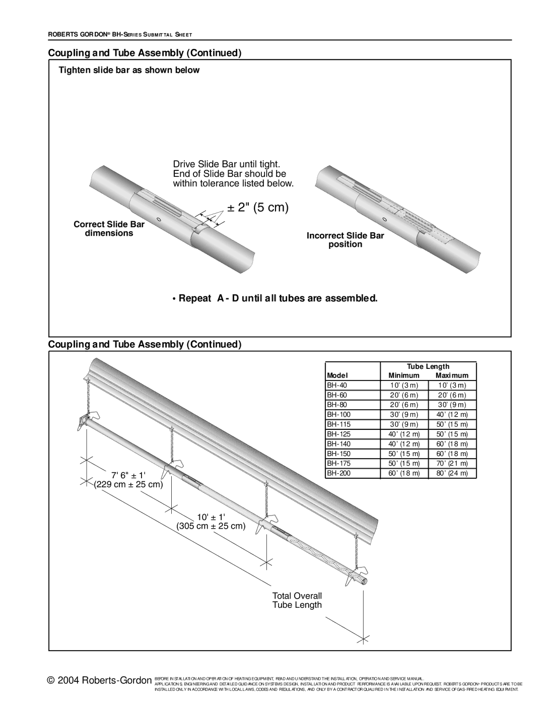
Tighten slide bar as shown below
| Drive Slide Bar until tight. |
| End of Slide Bar should be |
| within tolerance listed below. |
| ± 2" (5 cm) |
Correct Slide |
|
dimensions | Incorrect Slide |
| position |
•Repeat A - D until all tubes are assembled.
Coupling and Tube Assembly (Continued)
|
| Tube Length | |
| Model | Minimum | Maximum |
| 10’ (3 m) | 10’ (3 m) | |
| 20’ (6 m) | 20’ (6 m) | |
| 20’ (6 m) | 30’ (9 m) | |
| 30’ (9 m) | 40’ (12 m) | |
| 30’ (9 m) | 50’ (15 m) | |
| 40’ (12 m) | 50’ (15 m) | |
| 40’ (12 m) | 60’ (18 m) | |
| 50’ (15 m) | 60’ (18 m) | |
| 50’ (15 m) | 70’ (21 m) | |
7' 6" ± 1' | 60’ (18 m) | 80’ (24 m) | |
(229 cm ± 25 |
|
|
|
| 10' |
|
|
(305 | 25 cm) |
|
|
| Total Overall |
|
|
| Tube Length |
|
|
© 2004
APPLICATION S, ENGI NEERING AND DETAI LED GUID ANCE ON SYSTEMS DESIGN, INSTALLATI ON AND PRODUCT PERFORMANCE IS AVAI LABLE UPON REQUEST. ROBERTS GORDON® PRODUCTS ARE TO BE INSTALLED ONLY IN ACCORDANCE WI TH LOCAL LAWS, CODES AND REGULATIONS, AND ONLY BY A CONTRACTOR QUALI FIED I N THE I NSTALLATION AND SERVICE OF