ROBERTS GORDON ®
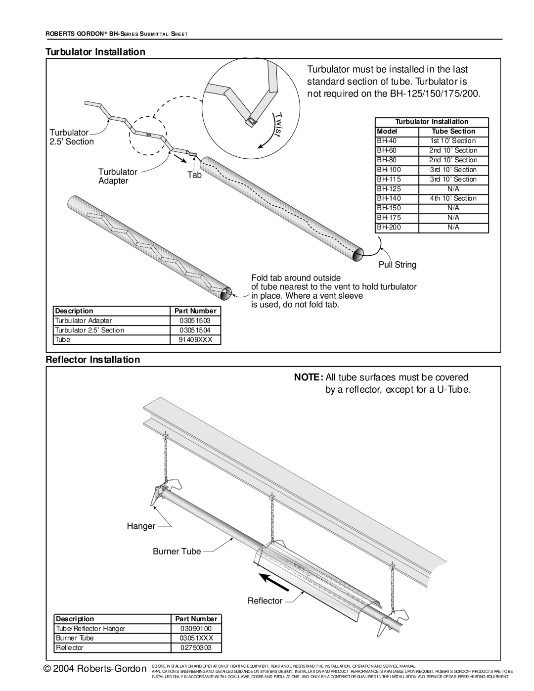
Turbulator Installation
Turbulator must be installed in the last standard section of tube. Turbulator is not required on the
|
| T |
|
|
|
| w | Turbulator Installation | |
Turbulator |
| i | Model | Tube Section |
| s | |||
2.5' Section |
| t |
| 1st 10’ Section |
|
| |||
|
|
| 2nd 10’ Section | |
|
|
| 2nd 10’ Section | |
| Turbulator | Tab | 3rd 10’ Section | |
| Adapter | 3rd 10’ Section | ||
|
| |||
|
|
| N/A | |
|
|
| 4th 10’ Section | |
|
|
| N/A | |
|
|
| N/A | |
|
|
| N/A | |
Description | Part Number |
Turbulator Adapter | 03051503 |
Turbulator 2.5’ Section | 03051504 |
Tube | 91409XXX |
Pull String
Fold tab around outside
of tube nearest to the vent to hold turbulator ![]()
![]() in place. Where a vent sleeve
in place. Where a vent sleeve
is used, do not fold tab.
Reflector Installation
NOTE: All tube surfaces must be covered by a reflector, except for a
Hanger
Burner Tube 
Reflector 
| Description | Part Number |
|
|
| ||
| Tube/Reflector Hanger | 03090100 |
|
| Burner Tube | 03051XXX |
|
| Reflector | 02750303 |
|
© 2004 | BEFORE IN STALLATI ON AND OPER ATI ON OF HEATI NG EQUIPMENT, READ AND U NDERSTAND THE INSTALLATION, OPERATIO N AND SERVICE MANUAL . |
APPLICATION S, ENGI NEERING AND DETAI LED GUID ANCE ON SYSTEMS DESIGN, INSTALLATI ON AND PRODUCT PERFORMANCE IS AVAI LABLE UPON REQUEST. ROBERTS GORDON® PRODUCTS ARE TO BE | |
| INSTALLED ONLY IN ACCORDANCE WI TH LOCAL LAWS, CODES AND REGULATIONS, AND ONLY BY A CONTRACTOR QUALI FIED I N THE I NSTALLATION AND SERVICE OF |