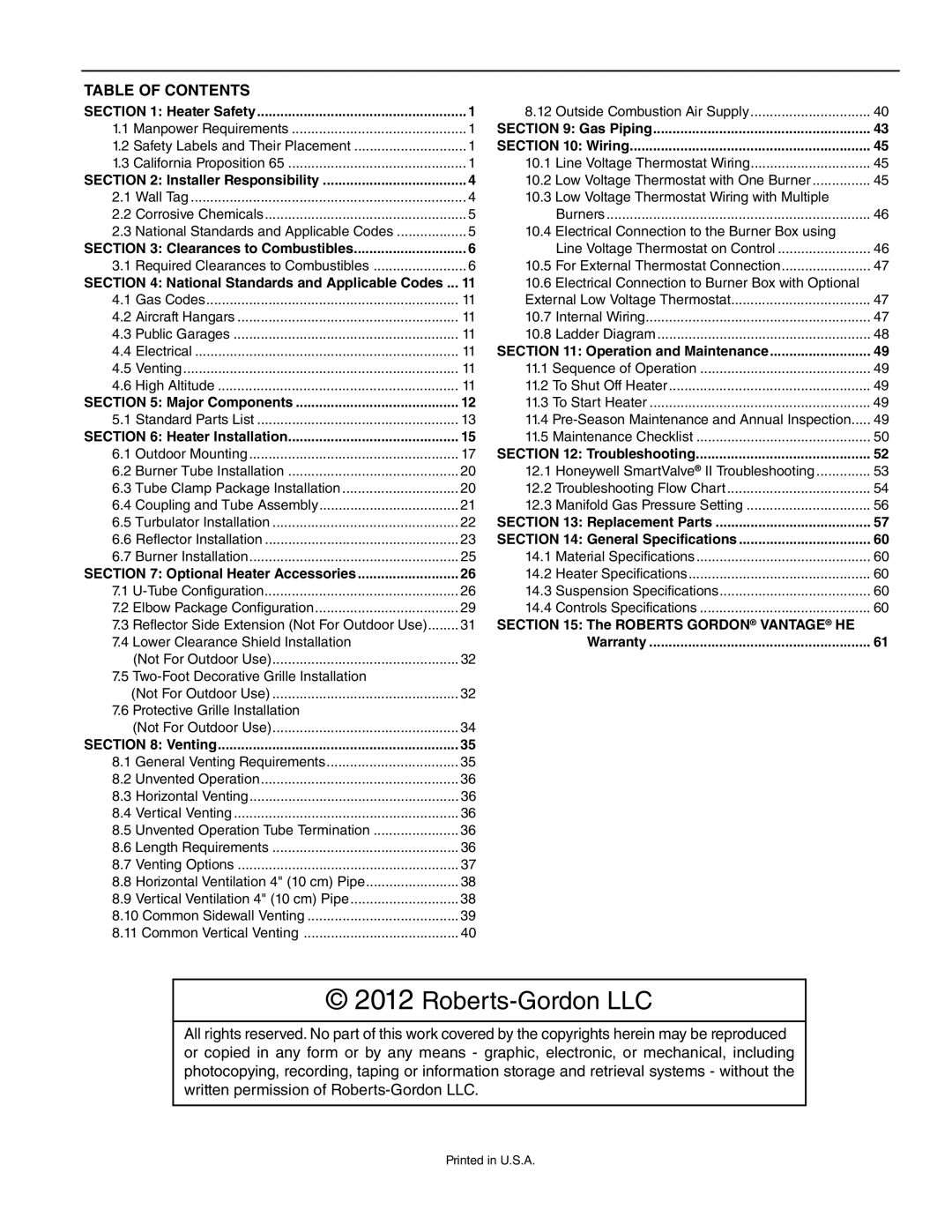
TABLE OF CONTENTS

SECTION 1: Heater Safety

1

8.12

Outside Combustion Air Supply

40

1.1 Manpower Requirements

1

SECTION 9: Gas Piping

43

1.2 Safety Labels and Their Placement

1

SECTION 10: Wiring

45

1.3 California Proposition 65

1

10.1

Line Voltage Thermostat Wiring

45

SECTION 2: Installer Responsibility

4

10.2

Low Voltage Thermostat with One Burner

45

2.1

Wall Tag

4

10.3

Low Voltage Thermostat Wiring with Multiple


2.2

Corrosive Chemicals

5


Burners

46

2.3

National Standards and Applicable Codes

5

10.4

Electrical Connection to the Burner Box using


SECTION 3: Clearances to Combustibles

6


Line Voltage Thermostat on Control

46

3.1

Required Clearances to Combustibles

6

10.5

For External Thermostat Connection

47

SECTION 4: National Standards and Applicable Codes ...

11

10.6

Electrical Connection to Burner Box with Optional


4.1

Gas Codes

11

External Low Voltage Thermostat

47

4.2

Aircraft Hangars

11

10.7

Internal Wiring

47

4.3

Public Garages

11

10.8

Ladder Diagram

48

4.4

Electrical

11

SECTION 11: Operation and Maintenance

49

4.5

Venting

11

11.1 Sequence of Operation

49

4.6

High Altitude

11

11.2 To Shut Off Heater

49

SECTION 5: Major Components

12

11.3 To Start Heater

49

5.1

Standard Parts List

13

11.4 Pre-Season Maintenance and Annual Inspection

49

SECTION 6: Heater Installation

15

11.5 Maintenance Checklist

50

6.1

Outdoor Mounting

17

SECTION 12: Troubleshooting

52

6.2

Burner Tube Installation

20

12.1

Honeywell SmartValve® II Troubleshooting

53

6.3

Tube Clamp Package Installation

20

12.2

Troubleshooting Flow Chart

54

6.4

Coupling and Tube Assembly

21

12.3

Manifold Gas Pressure Setting

56

6.5

Turbulator Installation

22

SECTION 13: Replacement Parts

57

6.6

Reflector Installation

23

SECTION 14: General Specifications

60

6.7

Burner Installation

25

14.1

Material Specifications

60

SECTION 7: Optional Heater Accessories

26

14.2

Heater Specifications

60

7.1 U-Tube Configuration

26

14.3

Suspension Specifications

60

7.2 Elbow Package Configuration

29

14.4

Controls Specifications

60

7.3 Reflector Side Extension (Not For Outdoor Use)

31

SECTION 15: The ROBERTS GORDON® VANTAGE® HE


7.4 Lower Clearance Shield Installation


Warranty

61


(Not For Outdoor Use)

32


7.5 Two-Foot Decorative Grille Installation


(Not For Outdoor Use)

32


7.6 Protective Grille Installation


(Not For Outdoor Use)

34


SECTION 8: Venting

35


8.1

General Venting Requirements

35


8.2

Unvented Operation

36


8.3

Horizontal Venting

36


8.4

Vertical Venting

36


8.5

Unvented Operation Tube Termination

36


8.6

Length Requirements

36


8.7

Venting Options

37


8.8

Horizontal Ventilation 4" (10 cm) Pipe

38


8.9

Vertical Ventilation 4" (10 cm) Pipe

38


8.10 Common Sidewall Venting

39


8.11 Common Vertical Venting

40


© 2012 Roberts-Gordon LLC

All rights reserved. No part of this work covered by the copyrights herein may be reproduced or copied in any form or by any means - graphic, electronic, or mechanical, including photocopying, recording, taping or information storage and retrieval systems - without the written permission of Roberts-Gordon LLC.

Printed in U.S.A.

Page 3
Image 3
Roberts Gorden HE-40, HE-60, HE-80, HE-175, HE-100, HE-150, HE-125 service manual Roberts-Gordon LLC

HE-125, HE-150, HE-100, HE-40, HE-175 specifications

Roberts Gordon is renowned for its innovative heating solutions, and among its standout offerings are the HE-125, HE-175, HE-100, HE-150, and HE-40 heaters. These products exemplify cutting-edge technology and efficiency designed for commercial and industrial applications.

The HE-125 and HE-175 variants are among the top-rated infrared heaters available. They utilize advanced infrared technology to provide direct heating to objects, reducing the need to heat the entire ambient air volume. This method results in energy savings while delivering consistent warmth where it's needed most. The HE-125 model has a heating capacity of 125,000 BTU, while the HE-175 pushes this to 175,000 BTU, making them suitable for larger spaces like warehouses and manufacturing facilities.

The HE-100 and HE-150 heaters are designed for flexibility and efficiency in a range of operational environments. These models support a wide range of input fuels including natural gas and propane, making them an adaptable choice for various setups. The HE-100 has an output of 100,000 BTU, and the HE-150 follows with 150,000 BTU. Both units are engineered with robust construction materials, ensuring durability and longevity, while also featuring advanced safety systems to prevent overheating and other hazards.

In contrast, the HE-40 heater stands out for smaller spaces, making it an ideal option for garages, workshops, or smaller commercial environments. With a capacity of 40,000 BTU, it effectively delivers consistent warmth without the excessive energy consumption associated with larger units.

All Roberts Gordon models prioritize energy efficiency, often meeting or exceeding current energy codes. They incorporate advanced control systems that allow precise temperature regulation, further optimizing energy use. Additionally, the heaters are designed with minimal maintenance needs, featuring durable components that ensure long-term reliability and performance.

With a legacy of quality and innovation, Roberts Gordon continues to set the standard in infrared heating technology. The HE series exemplifies a commitment to efficiency, safety, and versatility, making them suitable for a wide range of commercial and industrial applications. Whether heating a vast warehouse or a small workshop, these heaters provide reliable performance tailored to user needs.