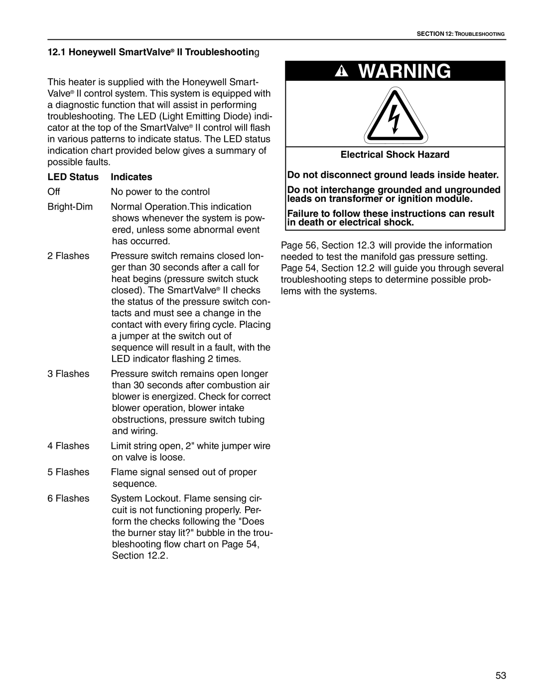
HE-125, HE-150, HE-100, HE-40, HE-175 specifications
Roberts Gordon is renowned for its innovative heating solutions, and among its standout offerings are the HE-125, HE-175, HE-100, HE-150, and HE-40 heaters. These products exemplify cutting-edge technology and efficiency designed for commercial and industrial applications.The HE-125 and HE-175 variants are among the top-rated infrared heaters available. They utilize advanced infrared technology to provide direct heating to objects, reducing the need to heat the entire ambient air volume. This method results in energy savings while delivering consistent warmth where it's needed most. The HE-125 model has a heating capacity of 125,000 BTU, while the HE-175 pushes this to 175,000 BTU, making them suitable for larger spaces like warehouses and manufacturing facilities.
The HE-100 and HE-150 heaters are designed for flexibility and efficiency in a range of operational environments. These models support a wide range of input fuels including natural gas and propane, making them an adaptable choice for various setups. The HE-100 has an output of 100,000 BTU, and the HE-150 follows with 150,000 BTU. Both units are engineered with robust construction materials, ensuring durability and longevity, while also featuring advanced safety systems to prevent overheating and other hazards.
In contrast, the HE-40 heater stands out for smaller spaces, making it an ideal option for garages, workshops, or smaller commercial environments. With a capacity of 40,000 BTU, it effectively delivers consistent warmth without the excessive energy consumption associated with larger units.
All Roberts Gordon models prioritize energy efficiency, often meeting or exceeding current energy codes. They incorporate advanced control systems that allow precise temperature regulation, further optimizing energy use. Additionally, the heaters are designed with minimal maintenance needs, featuring durable components that ensure long-term reliability and performance.
With a legacy of quality and innovation, Roberts Gordon continues to set the standard in infrared heating technology. The HE series exemplifies a commitment to efficiency, safety, and versatility, making them suitable for a wide range of commercial and industrial applications. Whether heating a vast warehouse or a small workshop, these heaters provide reliable performance tailored to user needs.

